
Technical information

commissioning
31
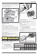
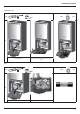
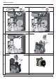
Test function and combustion analysis
The boiler has two pressure taps to measure the combustion gas
temperature, the combustive air and the concentrations of O
2
and CO
2
on the outside of the ue gas header.
To access these pressure taps, unscrew the screw which holds the
blanking cover and its seal together.
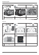
Checking the gas setting
To carry out analyses of combustion, the test function must be
activated.
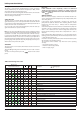
Maximum gas ow combustion analysis
Activate the test function at the maximum heating power, pushing
for 5 seconds the RESET until the yellow led 9 blinks (also 60°C led is
lit to indicate that Chimney is at max. CH absolute) The rotate the CH
knob to the min., intermediate position or max position it’s possible
to switch between min, max CH absolute and max DHW power
(respectively the 40°C, 60°C and 80°C are lit to indicate the power
level.
The function is automatically deactivated after 10 minutes or by
pressing the RESET button.
Wait for the boiler to stabilise before carrying out the combustion
analyses. Check the CO
2
value according to the table below.
Important: do not remove silencer 17
N.B. When the front combustion chamber panel is open, the CO
2
value drops by 0.3%.
CO
2
maximum
minimum
24 30 38
CO
2
(%)
G20 9.0 ± 0.2 9.0 ± 0.2 9.4 ± 0.2
G31 10.7 ± 0.2 10.0 ± 0.2 10.6 ± 0.2
Minimum gas ow combustion analysis
Activate the test function at minimum power in either heating or
domestic hot water production.
Wait for the boiler to stabilise before carrying out the combustion
analyses. Check the CO
2
value according to the table above.
Important: do not remove silencer 17
N.B. When the combustion chamber is open, the CO
2
value drops
by 0.3%.
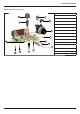
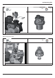
If the values taken di er from the table, adjust the gas valve following
the procedure described below.
To adjust the CO
2
value, remove cap, adjust the CO
2
content to ± 0.2 by
turning setting screw 51 (4 mm allen key)
- unscrew to lower the CO
2
value
- tighten to increase the CO
2
value
Set the content by turning the screw about a 1/4 of a turn then wait
after each change for approximately 1 minute for the CO
2
value to
stabilise, then repeat.
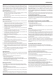
Once the settings and analyses are complete, exit test mode by
pressing Reset and reposition the blanking cover and its seal correctly.
Only a 2.5 key
must be used
50
Only a 4 key must be used
Gas setting
24 30 38
G20 G31 G20 G31 G20 G31
lower Wobbe index
15°C, 1013 mbar) (MJ/m3)
45.67 70.69 45.67 70.69 45.67 70.69
gas valve restrictor(ø) NO 3.80 NO 4.50 NO 5.25
gas ow max/min
(15°C, 1013 mbar)
(nat - m3/h) (GPL - kg/h)
max D.H.W 2.65 1.94 3.17 2.33 4.02 2.95
max C.H. 2.33 1.71 2.96 2.17 3.28 2.41
min 0.58 0.43 0.69 0.50 0.79 0.58
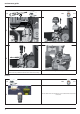
If the values taken di er from the table, adjust
the gas valve following the procedure described
below.
Adjust the CO
2
content to ± 0.2 by turning
setting screw 50 (2.5 mm allen key)
- tighten to lower the CO
2
value
- unscrew to increase the CO
2
value
Set the content by turning the screw about a
1/4 of a turn then wait after each change for
approximately 1 minute for the CO
2
value to
stabilise, then repeat.