
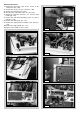
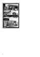
Operating instructions

19
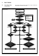
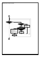
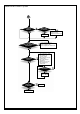
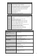
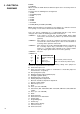
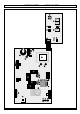
2. FAULT FINDING
TABLE
I and II
YES
YES
YES
NO
NO
IS THE
POWER L.E.D. AND
DISPLAY ON?
DOES A STOP CODE
APPEAR ON THE DISPLAY?
POSITION OF THE SUMMER/
WINTER SELECTOR
1. Check the fuses
2. Check the power supply to
the control panel
3. Check/replace the
ON/OFF button
4. Check the connection between
the main and display P.C.B.s
5. Check/replace the
main and display P.C.B.s
NO
PUSH THE ON/OFF
BUTTON TO ON
MAKE SURE THAT:
1. There is sufficient water in the system
2. The gas is turned on
3. The electrical supply is turned on
SUMMER
WINTER
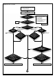
COMFORT
SELECTOR ON/OFF:
green L.E.D. on
YES: COMFORT ON
YES: COMFORT ON
Flow
temperature
<40°C
COMFORT
SELECTOR ON/OFF:
green L.E.D. on
Flow
temperature
>50°C
Flow
temperature
<40°C
Flow
temperature
>50°C
NO:
COMFORT OFF
NO:
COMFORT OFF
YES
NO
YES
NO
NO
YES
NO
YES
YES
YES
D.H.W.
IS BEING
DRAWN?
D.H.W.
IS BEING
DRAWN?
YES
NO
MUST
THE TIME CLOCK
AND/OR ROOM THERMOSTAT
BE ACTIVATED?
NO
NO
BUILT-IN
ELECTRONIC
ANTI-FROST DEVICE:
Is there a condition for it to be active?
(- flow temp. < 3°C
- outdoor temp. < -3°C (outdoor sensor optional)
- Jumper 4 selects the pump
for continuous
operation)
BUILT-IN
ELECTRONIC
ANTI-FROST DEVICE:
Is there a condition for it to be active?
(- flow temp. < 3°C
- outdoor temp. < -3°C (outdoor sensor optional)
- Jumper 4 selects the pump
for continuous
operation)
THERE IS NO CALL FOR PUMP OPERATION
THERE IS NO CALL FOR PUMP OPERATION
A
It is possible to detect and correct any defect by using the standard fault
finding diagrams described in this chapter.
2.1 FAULT FINDING GUIDE
(FLOW-CHARTS)
Model 24 MFFI