Including CUBE Room Sensor wireless G.C.N.: 47-116-93 (24 kW) G.C.N.: 47-116-94 (30 kW) G.C.N.
INDEX Overview ............................................................................................3 General Information ........................................................................4 Advice for the Installer....................................................................4 CE Labelling ......................................................................................4 Data Plate Symbols.........................................................................4 Safety Regulations ..
OVERVIEW These instructions are suitable for GENUS ONE NET boilers : Do not forgot to complete the Benchmark Commissioning Checklist! The Benchmark Scheme Benchmark places responsibilities on both manufacturers and installers.
OVERVIEW ATTENTION!! THE INSTALLATION AND FIRST IGNITION OF THE BOILER MUST BE PERFORMED BY GAS SAFE REGISTERED ENGINEER IN COMPLIANCE WITH GAS SAFETY (INSTILLATION & USE) REGULATIONS AND ALL OTHER NATIONAL REGULATIONS REGARDING INSTALLATION, AND IN CONFORMITY WITH ANY REQUIREMENTS ESTABLISHED BY LOCAL AUTHORITIES AND PUBLIC HEALTH ORGANISATIONS.
OVERVIEW SAFETY REGULATION Key to symbols: Failure to comply with this warning implies the risk of personal injury, in some circumstances even fatal Failure to comply with this warning implies the risk of damage, in some circumstances even serious, to property, plants or animals. Install the appliance on a solid wall which is not subject to vibration. Noisy operation. When drilling holes in the wall for installation purposes, take care not to damage any electrical wiring or existing piping.
OVERVIEW Handle the appliance with suitable protection and with care. Damage to the appliance or surrounding objects from shocks, knocks, incisions and squashing. During all work procedures, wear individual protective clothing and equipment. Personal injury caused by electrocution, falling splinters or fragments, inhalation of dust, shocks, cuts, puncture wounds, abrasions, noise and vibration.
PRODUCT DESCRIPTION CONTROL PANNEL 26/10/15 12:30 20,5° 10° 3 00 02 04 06 08 10 12 14 16 18 20 22 24 40° 1,5 bar COMFORT 70° AUTO Central Heating 1 2 3 4 5 a 6 b 7 b 8 9 10 c Legend: 1. Display 2. WIFI button (enable / disable / configure) 3. Domestic Hot Water adjustment button +/4. MODE button (Operation mode selection summer/winter) 5. COMFORT button 6. ON/OFF button 7. Auto button (To activate Thermoregulation) 8. RESET button 9. Heating temperature adjustument button +/10.
PRODUCT DESCRIPTION DISPLAY 26/10/15 12:30 20,5° 10° 3 Overall view 00 02 04 06 08 10 12 14 16 18 20 22 24 60° 82° 1,5 bar COMFORT 1 AUTO Riscaldamento attivo 26/10/15 12:30 Date and time 20 2 3 Keylock active D.H.W. set temperature and indication of the set temperature level 42° C.H. set temperature and indication of the set temperature level Warning scheduled maintenance 4 5 6 18 7 17 16 8 15 14 13 9 Heating operation set 10 12 Heating operation active D.H.W.
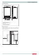
PRODUCT DESCRIPTION Overall Dimensions 200 200 120 25 180 745 745 120 67 67 65 150 28 65 (24) 385 -315 mod. 30-35 385 (30-35) A. Central Heating Flow B. Domestic Hot Water Outlet C. Gas Inlet D. Domestic Cold Water Inlet E. Central Heating Return 350 Minimum clearances In order to allow easy access to the boiler for maintenance operations, The boiler must be installed in accordance with the clearances stated below.
INSTALLATION INSTALLATION Reference Standards In the United Kingdom, the installation and initial start-up of the boiler must be by a Gas Safe registered installer in accordance with the installation standards currently in effect, as well as with any and all local health and safety standards i.e. Gas Safe. Flue Detailed information on flue assembly can be found in the “Connecting the Flue” section.
INSTALLATION Gas Supply The gas installation and tightness testing must be in accordance with the requirements of BS6891. Ensure that the pipe size is adequate for demand including other gas appliances on the same supply. Electrical Supply The appliance requires an earthed 230V - 50 Hz supply and must be in accordance with current I.E.E. regulations. It must also be possible to be able to completely isolate the appliance electrically.
INSTALLATION INSTALLATION overflow pipe. The condensate discharge pipe must have a minimum diameter of 22mm, must have a continuous fall and preferably be installed and terminated to prevent freezing. The discharge pipe must be terminated in a suitable position: 2. External termination of condensate drainage pipe via internal discharge branch (e.g. sink waste) and condensate siphon. i) Connecting into an internal soil stack (at least 450mm above the invert of the stack).
INSTALLATION Installing the Boiler Please check that you are familiar with the installation requirement before commencing work (pages 10 - 14).
INSTALLATION INSTALLATION Gas connection Make sure, using the labels on the packaging and the data plate on the appliance itself, that the boiler is in the correct country and that the gas category for which the boiler was designed corresponds to one of the categories available in the country where it will be used. The gas supply piping must be created and measured out in compliance with specific legal requirements and in accordance with the maximum power of the boiler.
INSTALLATION Graph representing the available circulation pump pressure ∆T20oC 600 500 400 mbar (c) To calculate the size of the heating installation, refer to the "Available pressure" graph below. 300 200 100 0 0 200 400 600 800 1000 1200 l/h Underfloor heating For appliances with underfloor heating, it is possible but not necessary to fit a safety thermostat onto the underfloor heating outlet.
INSTALLATION BEFORE THE DEVICE IS USED, FOR THE FIRST TIME THE TRAP MUST BE FILLED WITH WATER. The siphon is filled with water during deaeration procedure of the boiler (or heating system) - see p. 32 Ensure that the siphon contains water; if not, it must be refilled. Open the manual air vent (2) on the main exchanger until complete filling. Check again the system pressure on the pressure gauge.
INSTALLATION Connecting the Flue Flue System The provision for satisfactory flue termination must be made as described in BS 5440-1. The appliance must be installed so that the flue terminal is exposed to outdoor air. The terminal must not discharge into another room or space such as an outhouse or lean-to. It is important that the position of the terminal allows a free passage of air across it at all times.
INSTALLATION INSTALLATION Warning The exhaust gas ducts must not be in contact with or close to inflammable material and must not pass through building structures or walls made of inflammable material. When replacing an old appliance, the flue system must be changed. Important Ensure that the flue is not blocked. Ensure that the flue is supported and assembled in accordance with these instructions.
INSTALLATION Clamp Screws Seal Fig. 4 Fitting the 5” Flue (Ø 80 / 125 Horizontal/vertical) Once the boiler has been positioned on the wall, it is necessary to insert the Ø80/125 adaptor (Fig. 5) for both horizontal and vertical flue runs into the boiler flue socket (not supplied with flue kit - Part No 3318095). Push the adaptor onto the boilers flue connection, grease the seals then add extensions or elbows as required, secure the adaptor, using the clamp and screws provided.
INSTALLATION INSTALLATION Fitting the Coaxial Flue (Ø 60 / 100 Vertical) Note: See table for maximum and minimum flue runs. Contents: 1x Conical Adaptor (60/100mm) 1x Vertical Flue Kit (80/125mm) The vertical flue kit is supplied with a specially designed weather proof terminal fitted, it can be used either with a flat roof or a pitched roof.
INSTALLATION Fitting the Twin Pipe (Ø80 / 80) When siting the twin flue pipe, the air intake and exhaust terminals must terminate on the same wall, the centres of the terminals must be a minimum of 280 mm apart and the air intake must not be sited above the exhaust terminal (refer to Fig. 10). The air intake pipe can be run horizontally, however, the terminal and the final 1 metre of flue must be installed either horizontally or with a slight fall away from the boiler to avoid rain ingress.
INSTALLATION INSTALLATION 180 105 195 120 Fig. 9 For coaxial systems, the maximum development value, mentioned in the table below also takes into account an elbow. For twin flue systems the maximum development value, mentioned in the table includes the exhaust gas/air intake terminal. AIR INTAKE MUST NOT BE FITTED ABOVE THE EXHAUST AIR INTAKE Twin flue systems outlets should respect the following instructions: 1- Use the same ø 80 mm flue pipes for the air intakes and exhaust gas ducts.
INSTALLATION Table of flue gas exhaust duct lengths Maximum Extension Exhaust-air (m) Twin-pipe System Coaxial System FLUE TYPE Diameter of pipe (mm) GENUS ONE NET 30 30 35 C13 C33 C43 8 7 6 ø 60/100 C13 C33 C43 21 20 24 ø 80/125 S1 = S2 C13 36 = 36 30 = 30 23 = 23 C33 48 = 48 40 = 40 30 = 30 C43 36 = 36 30 = 30 23 = 23 C53 ø 80/80 S1 = Air intake S2 = Flue gas exhaust ø 80/80 S1 = S2 - Air intake and flue gas exhaust equal lengths S1 + S2 - Air intake and flue gas exhaust
INSTALLATION INSTALLATION WARNING! BEFORE PERFORMING ANY WORK ON THE BOILER, FIRST DISCONNECT IT FROM THE ELECTRICAL POWER SUPPLY USING THE EXTERNAL BIPOLAR SWITCH AND REMOVE THE FUSE. Peripheral unit connection To access peripheral unit connections carry out the following steps: - Disconnect the boiler from the power supply - Remove the casing - Rotate the control panel while pulling it forwards - Unhook the two clips to have access to the peripherical connections and the main P.C.B.
INSTALLATION Cube Room sensor (wireless) Connection To connect a room thermostat, read the instructions present in the kit delivered with the gas boiler. DO NOT CONNECT 240V TO ANY PERIPHERAL CONNECTIONS Room Thermostat / Remote Clock Connection To connect a room thermostat, it is necessary to: 1. Open the control panel 2. Loosen the cable clamp using a screwdriver and insert the wires leading from the room thermostat 3.
INSTALLATION INSTALLATION Electrical diagram For increased safety, ask a qualified technician to perform a thorough check of the electrical system. The manufacturer is not responsible for any damage caused by the lack of a suitable earthing system or by the malfunctioning of the electricity mains supply. GATEWAY WIFI Bk= Black Rd = Red Gr = Green Bl = Blue Br = Brown Wh = White Gry = Grey Detection/Ignition electrode NL 230 V 230 V 230 V 230 V T B TA2 BUS FLOOR SE TNK C.H.
COMMISSIONING Initial preparation Ariston Thermo UK Ltd support the benchmark initiative. On pages 77 and 78 of this manual the Benchmark Commissioning Checklist and Service interval Record can be found. It is important that this is completed in the presence of your customer, they are shown how to use it, and it is signed by them. Please instruct your customer that they must have this manual with them whenever they contact a service engineer or us.
COMMISSIONING FIRST IGNITION OPERATION Date . . . . . . . . . . . . . . . . . . . . . . . . Installer . . . . . . . . . . . . . . . . . . . . . 1. Check the electrical supply. 2. Check the type of gas (change the gas if necessary durung the Calibration procedure point 8). Complete ........................................... Complete ........................................... 3. Check the gas tightness. 4. Check the Flue 5. Fill the installation. Complete ........................................
COMMISSIONING Start-up procedure Press the ON/OFF button on the control panel to switch on the boiler: the display will light up. The initialisation procedure - indicated by the bar - begins. FIRST IGNITION CARRY OUT THE DEAERATION CYCLE AND AUTOMATIC CALIBRATION 1. Assicurarsi che: Initializing....... Wi-Fi bo Once the procedure is completed, the display will visualise the temperatures set for the central heating and domestic hot water circuits (display configuration: boiler base).
COMMISSIONING 3. ACTIVATION OF THE DISAERATION PROCEDURE AND AUTOMATIC CALIBRATION • Switch on the boiler (by pressing the ON/OFF button) and use the Mode button to select the standby mode, where no hot water or heating 00/00/00 00:00 requests are made. The display asks to Start the System air purge start the deaeration and and automatic calibration procedure calibration procedure. Press Ok to confirm • Press the OK button.
COMMISSIONING Table B Error Description Uncompleted calibration 01 - Flow Check Failed 01 Insufficient circulation. Make sure that: - the pump works correctly - the water pressure in the system is sufficient.
COMMISSIONING Minimum power 6. Adjusting the CO2 Intermediate Power Draw off the domestic hot water at the maximum water flow rate. Select the Chimney function by pressing the RESET button for 10 seconds. WARNING! When the cleaning function is activated, the temperature of the water coming out of the boiler may be more than 65°C.
COMMISSIONING Maximun Heating Power adjustment The maximum heating power can be adjusted to between the maximum power allowed by the boiler and the minimum power). The display shows the value between “100” and 0 of this interval. To check the maximum heating power, access menu 2/sub menu 3/parameter 1, check the value and, if necessary, modify it as indicated in the Gas Pressure table.
COMMISSIONING Gas Changeover The boiler is factory setted for the gas type indicated on the data plate. The adjustment, if necessary, must be performed by a Qualified Technician. It is not necessary a conversion kit, because the boiler has a auto adaptation gas system. Proceed as indicated: 1. Change parameter 202 to the new gas (see Technical Area). The display shows the error “The boiler must be calibrated”. 2. Perform the Calibration procedure and check the CO2 as indicated at page30. 3.
COMMISSIONING AUTO function This is a function which enables the boiler to automatically adapt its operation routine (the temperature of the heating elements) in line with the outdoor conditions, in order to achieve and maintain the requested room temperature conditions. Depending on the peripheral units connected and the number of zones controlled, the boiler adjusts its flow temperature automatically. The various corresponding parameters should therefore be set (see adjustments menu).
BOILER PROTECTION DEVICES Appliance shut-off conditions The boiler is protected from malfunctions by means of internal checks performed by the electronic P.C.B., which stops the boiler from operating if necessary. In the event of the boiler being shut off in this manner, a code appears on the control panel display which refers to the type of shut-off and the reason behind it.
BOILER PROTECTION DEVICES Table summarising error codes Central Heating circuit Display Description RESET X Multi-zone Heating 7 01 Zone 1 send sensor defective Zone 2 send sensor defective 1 01 Overheat 7 02 1 02 Pressure Sens Error 7 03 Zone 3 send sensor defective 7 11 1 03 1 04 1 05 Insufficient circulation 1 06 1 07 1 08 Insufficient water (request filling) 1 10 C.H. Flow temp. probe circuit open / short circuit 1 12 C.H. Return temp.
TECHNICAL AREA TECHNICAL AREA - reserved for qualified technician Accessing the Technical Area allows for setting/configuring the device according to the specific requirements of every installation procedure. It also provides important information relating to the efficient operation of the boiler. The Technical Area comprises various display windows that allow for directly accessing the parameters Intervening in each single product installation/configuration phase.
TECHNICAL AREA COMPLETE MENU STRUCTURE Tecnical Area Service code (reserved for qualified technicians) - Press the programming key b to select 234 and press the button . Language, date and time - Follow the instructions of the display. Press OK button at each entry to save COMPLETE MENU - The parameters relating to each individual menu are listed in the following pages.
2. SERVICE CODE Press th programming key b to select code 234 and press Ok COMPLETE MENU 0 NETWORK 0. 2 BUS NETWORK 0. 2. 0 Network Presence 2. Boiler Indication of the devices connected via BUS. 2. 0. 0. 4 BOILER USER INTERFACE 4. 0 Zone to be set by display from 1 to 3 (nr) 1 0. 4. 1 Backlight timing 10 0. 4. 2 Thermoregulation button 0 = OFF deactivation 1 = ON 2 BOILER PARAMETERS 2. 0 GENERAL 2. 0. 0 DHW Setpoint Temperature from 36 to 60 (°C) 2. Setting by DHW button 2 0.
2. 4. 4 Boost Time 2. only enabled with Room Thermostat on/off and temperature adjustment activated (parameter 421 or 521 or 621 on 01 = Basic temperature adjustment) This parameter can be used to set the delay time before the automatic increase in flow temperature, in steps of 4°C (max. 12°C). If the value of this parameter remains at 00 the function is not activated. 4. 5 Max PWM Pump from 75 to 100 100 2. 4. 6 Min PWM Pump 2. 4. 7 CHPressure detection device 2. 2. 4. 4. 2. 2. 5 5. 5. 2. 5.
2. 2 Slope from 1.0 to 3.5 (high temperature) from 0.2 to 0.8 (low temperature) 3.5 3.0 Flow Temperature °C 100 2.5 1.5 80 1.2 70 1.0 0.8 0.6 40 0.4 0.2 30 4. 2. 4. 2. 4. 2. 4. 2. 4. 4. 3 3. 5 0 -5 -10 -15 0.6 5. 5. 0 SETPOINT 0. 2 T set Zone 2 -20 °C from 35 to 82 (°C) (high temperature) from 20 to 45 (°C) (low temperature) To set only with Fixed Flow Temperaure of Thermoregulation (see 521) 5. 2 ZONE 2 SETTING 5. 2. 0 Zone 2 Temperature range 5. 2.
5. 5. 2. 5 Maximum CH Temperature Zone 2 2. 6 Minimum CH Temperature Zone 2 from 35 to 82 °C (Param. 520 = 1) from 20 to 45 °C (Param. 520 = 0) from 35 to 82 °C (Param. 520 = 1) from 20 to 45 °C (Param. 520 = 0) 82 ZONE 3 PARAMETER 0 SETPOINT 0. 2 T set Zone 3 from 35 to 82 (°C) 70 To set only with Fixed Flow Temperaure of Thermoregulation (see 521) 2 ZONE 3 SETTING 2. 0 Zone 3 Temperature 0 = from 20 to 1 range 45°C (low temperature) 1 = from 35 to 82°C (high temperature) 1 0 = Fixed Flow 2.
8. 2. 4 Diverter valve position 8. 8. 8. 8. 8. 8. 8. 8. 8. 8. 2. 2. 2. 3 3. 3. 3. 3. 3. 3. 8. 8. 4 4. 8. 8. 5 5. 0 = D.H.W. 1 = Central Heating 5 D.H.W. Flow Rate (l/min) 7 Pump Modulation % 8 Gas Power (kW) BOILER TEMPERTURE 0 CH Flow set Temperature(°C) 1 CH Flow Temperature(°C) 2 CH Return Temperature(°C) 3 DHW Temperature (°C) 4 < Not Available> 5 Outdoor temperature (°C) Only with external sensor connected STORAGE 2 D.H.W.
MAINTENANCE Important Maintenance is an essential part of the safe and efficient operation of the boiler and ensures its durability. It should be performed according to the instructions given in current legislation. Perform combustion analysis regularly in order to check the operating efficiency of the boiler and to make sure any polluting substances released are within the boundaries set by current legislation.
MAINTENANCE GUIDE Cleaning the trap The trap is accessed by emptying the condensate bowl located in the bottom section. Wash with water and detergent. Replace the condensate collection bowl in its housing. NB: In the event of prolonged use of the appliance, the trap must be filled before being used again. A lack of water in the trap is dangerous and may cause products to be released into the atmosphere.
MAINTENANCE GUIDE 1. GENERAL ACCESS Remove the front panel 1.0 Disconnect the boiler Before beginning maintenance work: a. Disconnect the appliance from the electricity supply. Press the ON/OFF button and wait 1 minute (the 3-way valve turn on Stand-by position) ATTENTION!! With the 3-way valve on heating position is not possible to remove the motor. Turn the external bipolar switch to the “OFF” position. b. Close the gas valve and the central heating and domestic hot water system valves. 2 1 1.
MAINTENANCE GUIDE 2. ELECTRICAL UNIT 2.2 Fuse 2.
MAINTENANCE GUIDE 2.3 Main P.C.B. 2.4 Display P.C.B. Tools Tools TIME 5 min After opening the control box, disconnect the elctrical plug connections TIME 5 min Unscrews the two screws and pull the assembly towards you Front 1 1 Unhook and remove the P.C.B.
MAINTENANCE GUIDE 3. HYDRAULIC UNIT Rotate clockvise to unhook the locking ring. 3.1 RIGHT HAND HYDRAULIC BLOCK ASSEMBLY 1 9 2 8 4 3 2 7 6 11 Remove the 3 way valve motor. 10 5 Legend: 1 - Diverter valve motor 2 - Diverter valve 3 - By-pass 4 - D.H.W. flow switch assembly 5 - C.H. drain valve 6 - Central heating filter 7 - Pump 8 - Water pressure sensor 9 - Auto air vent 10 - Central Heating return 11 - Cold water inlet (D.H.W.) 3 3.2.
MAINTENANCE GUIDE 3.3 Draining 3.5 Primary water pressure sensor Tools Tools TIME TIME 5 min Turn the drain valve anti-clockwise to open and drain the water from the boiler Drain the boiler (see 3.3). Slide the fixing clip, (it is held captive) unplug the electrical connector and lift the sensor from the assembly. 1 1 3.4 Automatic air vent Tools 2 TIME 5 min 5 min Drain the boiler (see 3.3). Unscrew anticlockwise the AAV from the assembly.
MAINTENANCE GUIDE 3.6 By-pass assembly 3.7 Pump Tools Tools TIME 5 min Drain the boiler (see 3.3). Remove the clip and pull the assembly towards you 1 TIME 10 min Drain the boiler (see 3.3).
MAINTENANCE GUIDE Remove the sensor (see 3.5) 3.8 C.H. Filter Tools TIME Drain the boiler (see 3.3). Remove the clip and remove the pressure gauge 4 1 Remove the AAV (see 3.
MAINTENANCE GUIDE 3.9 D.H.W. Flow switch assembly Tools TIME 10 min Drain the boiler (see 3.3). Remove the clip and pull the flow switch assembly upward.
MAINTENANCE GUIDE 3.10 LEFT HAND HYDRAULIC BLOCK ASSEMBLY 4 3 1 2 3 Legend: 1 - Safety valve 2 - Central heating flow 3 - Domestic hot water outlet 4 - Secondary heat exchanger 3.10 Secondary heat exchanger 4 Tools TIME 10 min Drain primary and domestic hot water circuits. Remove the silencer.
MAINTENANCE GUIDE 3.11 Condensate trap 3.12 Safety valve Tools Tools TIME 5 min Disconnect the condensate discherge pipe from the bottom of the boiler. Unscrerw the two screws. TIME Drain the boiler (see 3.3). Disconnect the discharge pipe.
MAINTENANCE GUIDE 3.15 Temperature sensors 3.16 Manual Air vent Tools Tools TIME TIME 5 min NTC1 1 1 NTC2 Unplug the electrical connectors 2 2 Remove the clip and the temperature sensor IMPORTANT ! Do not use conducting paste for the contact sensors because it will alter the resistance value. TEMPERATURE 0 10 20 25 30 40 50 5 min Drain boiler (see 3.
MAINTENANCE GUIDE Disconnect the cable of the electrode. 3.17 Main heat exchanger Remove the four nuts and remove the burner unit Tools TIME 20 min Drain boiler (see 3.3) Remove the silencer 3 1 4 Isolate the gas supply and disconnect the gas pipe.
MAINTENANCE GUIDE Disconnect the plastic pipes from the manual air vent.
MAINTENANCE GUIDE 4.
MAINTENANCE GUIDE 4.1 Electrode (detection and ignition) 4.2 Burner Tools Tools TIME Unplug the electrode on the control box Remove the screws and pull the electrodes towards you. 1 TIME 5 min Remove the silencer 1 Isolate the gas supply. Disconnect the gas pipe. 2 2 Disconnect the cable of the electrode.
MAINTENANCE GUIDE Pull the assembly towards you Remove the ceramic fibre. Remove the four screws and pull the burner toward you. Always replace the burner gasket (*). (*) 4 6 Remove the two screws and remove the electrode Verify and replace the other gaskets if they are damaged or showing signs of deterioration 4.3 Fan Tools 4 TIME Remove the silencer (see 4.3 - 1) Isolate the gas supply. Disconnect the gas pipe (see 4.
MAINTENANCE GUIDE 4.4 Gas Valve Remove the three screws to free the fan. Tools TIME 15 min Remove the two screws under the boiler and disconnect the gas pipe on the top of the gas valve 2 1 Remove the gas valve Remove the three nuts.
MAINTENANCE GUIDE 5. ANNUAL MAINTENANCE Plate heat exchanger Maintenance Interval: As necessary How: To measure specification of DHW performance.
MAINTENANCE GUIDE Primary Heat exchanger Maintenance Interval: Annually How : Visual inspection / Clean as necessary Condensate trap Maintenance Interval: Annually or after cleaning primary heat exchanger How : Visual inspection / Clean as necessary / Add water before replacing Pump Maintenance Interval: At the first ignition and annually How: Check that the AAV is open / Visual inspection / Clean as necessary / 65
POWER SPECIFICATIONS GENERAL TECHNICAL DATA Model: 24 Max/min nominal calorific flow rate (Pci) ............................ Qn kW Max/min nominal calorific flow rate (Pcs) .......................... Qn kW kW 26,0 / 2.5 30.0 / 3.0 34.5 / 3.5 kW 28.9 / 2.8 33.3 / 3.3 38.3 / 3.9 Max/min power output (80°C-60°C) .................................... Pn kW Max/min power output (50°C-30°C) .................................... Pn kW 21.5 / 2.3 23.6 / 2.6 27.5 / 2.8 30.3 / 3.1 30.3 / 3.3 33.
TECHNICAL DATA ErP Data - EU 813/2013 Model: GENUS ONE NET 24 Condensing boiler yes/no Low-temperature boiler: yes/no B1 boiler yes/no Cogeneration space heater yes/no Combination heater yes/no Contact details ( Name and address of the manufacturer or its authorised representative) 30 35 yes no no no yes yes yes no no no no no no yes yes ARISTON THERMO S.p.A. Viale A.
TECHNICAL DATA PRODUCT FICHE - EU 811/2013 Brand Model GENUS ONE NET Declared load profile 24 30 35 XL XL XXL Seasonal space heating energy efficiency class A A A Water heating energy efficiency class A A A Power output Pn kW 22 28 31 Annual energy consumption QHE GJ 38 48 54 kWh 49 49 50 GJ 18 18 23 Seasonal space heating energy efficiency ηs % 94 94 94 Water heating energy efficiency ηWH % 86 85 86 dB 49 54 51 Annual electricity consumption AEC Annual fuel
TECHNICAL DATA Package fiche 1 I 3 4 + + + + 2015 2 II 6 A A XL 5 A+++ A++ A+ A B C D E F G XL A+++ A++ A+ A B C D E F G A+ 7 A++ Instructions for filling the label for packages of space heater (or combination heater), temperature control and solar device. 1. supplier’s name or trademark; 2. supplier’s model identifier; 3. the seasonal space heating energy efficiency class of the space heater, already filled; 4.
TECHNICAL DATA PACKAGES OF COMBINATION HEATER, TEMPERATURE CONTROL AND SOLAR DEVICE The fiche for packages of combination heater, temperature control and solar device shall contain the elements set out in points (a) and (b): a) the elements set out in Figure 1, respectively, for evaluating the seasonal space heating energy efficiency of a package of combination heater, temperature control and solar device, including the following information: - I: the value of the seasonal space heating energy efficiency of
TECHNICAL DATA Figure 1 1 Seasonal space heating energy efficiency of boiler ‘I’ Temperature control From fiche of temperature control 2 ✂ Class I = 1%, II = 2%, III = 1,5%, IV = 2%, V = 3%, VI = 4 %, VII = 3,5%, VIII = 5% Supplementary boiler From fiche of boiler % + % Seasonal space heating energy efficiency (in %) 3 ( % - ‘I’ ) x 0,1 = Solar contribution - From fiche of solar device 2 3 Collector size ( in m ) Tank volume ( in m ) ( ‘III’ x + ‘IV’ x Collector efficiency ( in %) ) x 0
TECHNICAL DATA Figure 5 Water heating energy efficiency of combination heater 1 % ‘I’ Declared load profile: Solar contribution - From fiche of solar device (1,1 x ‘I’ - 10%) x ‘II’ - ‘III’ - ‘I’ = Water heating energy efficiency of package under average climate + ✂ Auxiliary electricity 2 % 3 % Water heating energy efficiency class of package under average climate C B A + ++ +++ G F E D M < 27 % ≥ 27 % ≥ 30 % ≥ 33 % ≥ 36 % ≥ 39 % ≥ 65 % ≥ 100 % ≥ 130 % ≥ 163 % L < 27 % ≥
GAS BOILER SYSTEM COMMISSIONING CHECKLIST This Commissioning Checklist is to be completed in full by the competent person who commissioned the boiler as a means of demonstrating compliance with the appropriate Building Regulations and then handed to the customer to keep for future reference. )DLOXUH WR LQVWDOO DQG FRPPLVVLRQ DFFRUGLQJ WR WKH PDQXIDFWXUHU¶V LQVWUXFWLRQV DQG FRPSOHWH WKLV %HQFKPDUN &RPPLVVLRQLQJ &KHFNOLVW ZLOO LQYDOLGDWH WKH ZDUUDQW\ 7KLV GRHV QRW DIIHFW WKH FXVWRPHU¶V VWDWXWRU\ ULJKWV &X
SERVICE RECORD It is recommended that your heating system is serviced regularly and that the appropriate Service Interval Record is completed. Service Provider %HIRUH FRPSOHWLQJ WKH DSSURSULDWH 6HUYLFH 5HFRUG EHORZ SOHDVH HQVXUH \RX KDYH FDUULHG RXW WKH VHUYLFH DV GHVFULEHG LQ WKH PDQXIDFWXUHU¶V LQVWUXFWLRQV $OZD\V XVH WKH PDQXIDFWXUHU¶V VSHFL¿HG VSDUH SDUW ZKHQ UHSODFLQJ FRQWUROV SERVICE 01 'DWH SERVICE 02 (QJLQHHU QDPH (QJLQHHU QDPH &RPSDQ\ QDPH &RPSDQ\ QDPH 7HOHSKRQH 1R 7HOHSKRQH 1R
ITALIAN DESIGN Ariston Thermo UK Ltd ariston.co.