EN TECHNICAL MANUAL COFFEE MACHINE All the parts included in this document are the property of Indesit Company S.p.A. All rights reserved. This document and the information it contains are supplied without liability for possible errors or omissions; no part of this document can be reproduced, used or disclosed without written permission or without being authorised by the terms of a contract clause. Service Manual P0055 Coffee Machine - 2006 Edition 2006.08.
EN CONTENTS OF THIS MANUAL: NOTE FOR THE SERVICE ENGINEER. This manual is a supporting document for technical personnel. It contains a description of the various product types, the general operating principle, and indications concerning assistance. Service Manual P0055 Coffee Machine - 2006 Edition 2006.08.
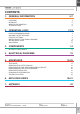
EN CONTENTS 1. GENERAL INFORMATION 4-7 PRODUCT KEY OVERVIEW INTERFACE GENERAL INFORMATION TECHNICAL DATA 4 4 5 5 6 2. OPERATING LOGIC 7-13 OPERATING MODES USER PROGRAMMING MODE GROUND COFFEE DOSAGES FACTORY SETTINGS WATER CIRCUIT FUNCTIONAL DIAGRAM SBS DELIVERY VALVE AQUA PRIMA 7 7 7 8 9 10 12 3. COMPONENTS 14 INTERNAL COMPONENTS 14 4. ELECTRICAL DIAGRAMS 15 WIRING DIAGRAM 15 5.
EN TYPE 1. PRODUCT TYPE: 1.1. PRODUCT KEY: MCA 16: MCA 15 NA P: M=machine C=coffee A=automatic 16=index number M=machine C=coffee A=automatic 15=index number N=North A=America P=connection to water supply 1.2. OVERVIEW: Description of the appliance 6 2 7 8 1 3 4 10 5 12 11 Ref. description 1 2 3 4 5 6 Water tank Coffee beans hopper Main power switch Grind adjustment Brew unit Front (control) panel Service Manual P0055 Coffee Machine - 2006 9 Ref.
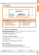
EN TYPE 1.3. INTERFACE 13 14 15 16 17 18 19 20 21 Ref. description 13 14 15 16 17 PROGRAMMING/EXIT select button PAGES forward button SELECT/CONFIRM button DOUBLE COFFEE selection button LUNGO COFFEE select button 22 Ref. description 18 19 20 21 22 NORMAL COFFEE select button ESPRESSO select button HOT WATER select button STEAM select button DESCALE select button 1.4.
EN TYPE 1.5. PRODUCT TECHNICAL DATA: Power supply and consumption: 230 V~; 50 Hz; 1250 W 120 V; 60 Hz; 1250W 100 V; 60 Hz; 1250 W Safety devices 2 safety thermostats set at 170°C with heat exchanger Temperature control NTC sensor Coffee heating element Stainless steel heat exchanger - (1090W), for coffee or hot water.
EN 2. OPERATING LOGIC 2.1. OPERATING MODES: The appliance can operate in the following modes: • Diagnostics Mode: this mode allows service engineers to adjust operating and service parameters. This menu contains all the user menu • Test Mode: Used by ser vice personnel to check operation of the appliance and its main components. OPERATION • User Programming Mode: From the user menu you can change appliance programming as described in the instruction booklet.
EN 2.3.2. DOSAGE PROGRAMMING FOR THE ENGINEER In “Test” mode you can increase the rpm of the coffee grinder in correspondence with each aroma type (LIGHT, REGULAR, STRONG) by 2.5 rpm. Level/Aroma type LIGHT REGULAR STRONG 0 1 2 45 47.5 50 50 52.5 55 55 57.5 60 OPERATION The available levels are as follows: 2.4.
EN 2.5.
EN 2.6. SBS VALVE OPERATION Beverage dispensing The SBS delivery valve (see fig. 2), which is adjustable using the knob, serves to alter (increase or decrease depending on the knob setting) the flowrate of water for brewing in the unit. This serves to alter the coffee brewing time (extraction time) and consequently the intensity of flavour, while maintaining the quantity of crema constant. Fig.
EN Knob in MAX position SBS The difference in delivery rate is approx. 2.5 times (and therefore VERY obvious!!).
EN 2.7. AQUA PRIMA If the “aqua prima” function is disabled, the electronic control system performs a pulse count of the turbine, recording one pulse every revolution. If the “aqua prima” function is enabled, the electronic control system performs a pulse count of the turbine, recording one pulse every 2 revolutions.
EN 2. The ion exchanger reduces lime scale deposits and eliminates heavy metals and suspended substances from tap water. 3. A special porous filter intercepts undesirable microparticulate. 4. The corpuscular filter, used as a connection between reservoir and appliance, filters the water, retaining any suspended substances and impurities. As seen in the following graph, the “Aqua Prima” filter reduces water hardness by up to 50 %. The water used to brew the coffee is filtered immediately prior to delivery.
EN 3. COMPONENTS: 3.1. INTERNAL COMPONENTS 1 3 COMPONENTS 2 9 4 8 5 6 7 Ref. description 1 2 3 4 5 Coffee grinder Power Board Coffee grinder motor Boiler Thermostat Service Manual P0055 Coffee Machine - 2006 Ref. description 6 7 8 9 Steam boiler Relief and compensation valve Pump Solenoid valve Edition 2006.08.
EN 4. WIRING DIAGRAMS: WIRING DIAGRAMS 4.1. WIRING DIAGRAM Service Manual P0055 Coffee Machine - 2006 Edition 2006.08.
EN 5. ASSISTANCE: 5.1. DIAGNOSTICS MODE Diagnostics mode includes all the options of the user programming function plus the “programmer”* menu, whereby service personnel can access protected parameters that are not accessible by the end user. Some of these parameters are editable, others are read-only.
EN 5.2. TEST MODE This menu provides the facility to check operation of the main components of the machine. To access test mode: To access this menu switch the machine on and select the following sequence STEAM DECALCIFY - STEAM- DECALCIFY within an interval of 3 seconds. When you access Test mode a window will be displayed containing all the information on the installed software version. The user can access the various different levels by pressing the MENU button.
EN Microswitches and sensors check DESCRIPTION ACTIVE INACTIVE NOTES 1 Gearmotor WORK microswitch Dispenser in WORK position Dispenser not in WORK position 2 Gearmotor HOME microswitch Dispenser in HOME position Dispenser not in HOME position 3 Front control panel microswitch Panel closed Panel open 4 GROUNDS DRAWER microswitch Grounds drawer present Grounds drawer not present 5 BREW UNIT microswitch Present Absent 6 DOOR microswitch Door open 7 FLOWMETER 8 WATER LEVEL in reser
EN Check COMPONENT FUNCTIONS BUTTON FUNCTION Note: certain loads are equipped with safety devices that may deactivate them to avoid possible damage. SAFETY INFORMATION UP The brew unit moves up WORK microswitch must be deactivated. The grounds drawer microswitch must be active. The door must be closed Motor current [mA] DOWN The brew unit moves down HOME microswitch must be deactivated. The grounds drawer microswitch must be active.
EN Level M3: Tests on coffee grinder This level allows the service engineer to check operation of the coffee grinder. The first line shows a description of the level and a space for analog information, if present (red circle). The second line shows whether or not the load is active (blue circle). Additional information is shown in the red circle and the flashing “X” (green circle). When the coffee grinder is operating (UP button) the speed is shown in rpm (red circle ) and the “X” flashes (green circle).
EN 1. Remove the drawer 4. Open the front door and remove the coffee assy by pressing the button shown in the photo 2. Remove the drawer support 5. Remove the screws shown in the photo B B ASSISTANCE 5.3. DISASSEMBLY OF THE OUTER CHASSIS A A 3. Undo screws “A” Service Manual P0055 Coffee Machine - 2006 6. Undo screws “A” and press the interlocking tabs then push them outwards (this operation must be performed also on the other side of the chassis) Edition 2006.08.
EN 10. To remove the gear for opening of the front panel detach the spring and withdraw the gear ASSISTANCE 7. Slide the appliance out of the outer chassis as shown in the photo 8. Undo the screw shown in the photo to remove the LH insert 9. Undo the screws shown in the photo to remove the RH insert Service Manual P0055 Coffee Machine - 2006 Edition 2006.08.
EN 5.4. REMOVING THE CASE AND COMPONENTS SUPPORT 1. Undo the screws shown in the photo on the RH and LH sides ASSISTANCE Clip 2. Undo the screws (shown above and right) and detach the steam hose by removing the Clip. 3. Undo the screws shown in the photo at the rear of the machine Service Manual P0055 Coffee Machine - 2006 4. Remove the cover as shown in the photo Edition 2006.08.
EN A C B ASSISTANCE 5. Remove wire tie “B” and extract connector “A” and Fastons “C” 6. Lift the components suppor t clear of the chassis 7. Chassis Service Manual P0055 Coffee Machine - 2006 8. Plate Edition 2006.08.
EN ASSISTANCE 9. Remove the wire tie 10. Remove the upper plate by lifting it Service Manual P0055 Coffee Machine - 2006 Edition 2006.08.
EN 5.5. REMOVING THE COFFEE GRINDER 1 2 ASSISTANCE 1. Undo the screws shown by the arrow (Note: When reassembling the coffee grinder remember to refit the two vibration dampers “1” which are wrapped around motor “2”) 2. Remove the coffee grinder 3. When reassembling the coffee grinder use caution when repositioning the seal shown in the photo Service Manual P0055 Coffee Machine - 2006 Edition 2006.08.
EN Disassembling the grinder burrs released A D (upper burr disassembly) Once the burr is detached it can be removed from its support. ASSISTANCE B C 4 To remove the upper burr “A” (disassemble the pack) turn it counterclockwise as shown in the first photo, with the aid of the ringnut “B” until tooth “C” is aligned with slot “D” Service Manual P0055 Coffee Machine - 2006 Edition 2006.08.
EN released After releasing the lower burr it can be removed from the relative support. (lower burr disassembly) Remove all coffee residues with a small flat-bladed screwdriver, a jet of compressed air, and a vacuum cleaner. Rotate the burr anticlockwise, using a small flatbladed screwdriver to prise it off as shown in the first figure. Service Manual P0055 Coffee Machine - 2006 The upper and lower burrs are made of ceramic material and are identical. N.
EN 1. Undo the four fixing screws of the motor flange. 4. Remove the sensor from the flange seat by pressing on the anchoring tab. 2. Remove the sensor support from the flange seat with the aid of a small screwdriver (as shown in the figure). 5. Disconnect the motor power cables. ASSISTANCE Disassembly of the coffee grinder motor 6. If the gear is damaged, remove it using a 10 mm wrench and a 7 mm wrench to unscrew the locknut. 3. Remove the rubber plug from the motor flange.
EN 7. Fit the new gear and mesh it with the spindle pinion; now secure the gear with the washer and locknut. 11. Apply grease also to the teeth of the worm gear on the grinder motor shaft. 12. Couple the motor flange with the rest of the unit as shown in the figure. ASSISTANCE 8. Tighten the nut onto the brass spindle shaft with the 7 and 10 mm wrenches. 9. Apply grease to all the gear teeth.. 10. Smear the grease uniformly and generously over the entire gear.
EN 5.6. REMOVING THE BOILERS Steam boiler A D B D 1. Undo screw “A” and the two nuts “B”. Remove the two Teflon hoses. Remove the heating element protection “C” and detach the two Faston connectors “D”. 2. To remove the steam boiler unscrew the locknuts and withdraw the Teflon hoses. Service Manual P0055 Coffee Machine - 2006 ASSISTANCE C 3. Undo the screw shown in the photo Edition 2006.08.
EN 1. To remove the coffee boiler undo the three screws shown in the photo. 4. Remove the Fastons of the safety thermostats 2. Remove the boiler from the plate assy. 5. To replace the thermostats loosen the screw shown in the figure 3. Remove the 4 Faston connectors from the heating element terminals Service Manual P0055 Coffee Machine - 2006 ASSISTANCE Coffee boiler 6. Remove the fixing clip and remove the Teflon hose that connects the pump to the boiler 7.
EN 5.7. CHANGING THE GEARMOTOR A E B F G 1. Remove cover (A) by undoing the three screws. A C B 2. Undo the two screws and remove boiler spigot (B) 4.
EN A H C L 5. Install the motor and drive shaft, fitting guides (L) in their location 8. Refit protective cover (C) and secure with the relative screws G B D B P 6. Fit gear (B), taking care to ensure that the arrow stamped on the gear is within the opening containing pin (P). 7. Fit the gear that meshes with the transmission shaft. Service Manual P0055 Coffee Machine - 2006 9.
EN 5.8. TROUBLESHOOTING PROBLEMS CAUSES SOLUTIONS The machine fails to switch on The machine is disconnected from the power supply Check the connection to the power supply. Coffee is insufficiently hot Cups are cold Warm cups with hot water. No hot water or steam supplied Steam wand blocked Extract steam wand by pulling downwards and then wash it. Coffee is delivered too slowly Coffee grind is too fine Brew unit dirty Change coffee blend Turn grind adjustment knob to a higher value setting.
EN 0 1 2 3 4 5 6 9 10 11 12 13 14 15 16 17 18 19 20 instruction manual coffee machine chassis coffee machine left upright enclosure lower/upper insert enclosure side/rear insert water recovery tray cover enclosure side/front insert coffee machine right upright torx screw, galvanized 2.9x6.5 washer d11 x 0.
EN torx screw, m 3x20 iso 14580 washer, uni 8842 a3 s/steel torx screw, m 3x8 din 7500 torx screw, k 30x8 wn 1452 washer, uni 8842 a6 door hinge bush door inner plate coffee delivery hose rear plug coffee delivery hose seal coffee delivery hose coffee dispenser support coffee dispenser seal (h2.5) door button support door button clip door button torx screw, k 30x8 Teflon hose holder insert joint support O-ring 117 silicone semi-spherical seal torx screw, m 4x10 head d=8x1.
1 2 3 4 5 6 7 8 9 10 11 12 13 14 15 16 torx screw, k 30x8 wn 1452 coffee machine main PCB w/connect level sensor 2-pin connector assy. control PCB protection water valve support tray terminal board torx screw, k 30x8 coffee hopper coffee container closing insert coffee machine containers support plug for flat cable channel cover flat cable channel cover microswitch coffee container rear cover coffee container front cover coffee container Service Manual P0055 Coffee Machine - 2006 Ref.
Ref. description 1 2 3 4 5 6 7 8 9 10 coffee machine container support turbine support microswitch pin clip front panel rotation pin water container rear cover water container cover water container front cover float assy, w/magnet float support water valve union Service Manual P0055 Coffee Machine - 2006 VIEWS EXPLODED EN Ref. description 11 12 13 14 15 16 17 18 19 20 Teflon hose 5x7 l=60 mm water container external filter assy.
EN 90° pump inlet union hose clip d=9.5mm silicone hose 5x8 70sr pump support eaton magic ulka pump ep5/s gw 230v-50hz 2-pole pump connector O-ring 2031 compensation valve assy. and 16 bar relief valve hose clip d=4 O-ring 2015 silicone torx screw, k 35x16 pump support silicone hose 5x10 60 shore Teflon union-nut-prot. assy.
EN increase screw coffee grinder upper support O-ring metric 0530-15 ceramic burr 48x28 increase screw pin m4-m6 ceramic burr lower support thrust bearing felt ring od=45.4 id=39.4 h=4 ground coffee outlet support body balancing washer 21.8x14x0.25 radial bearing grinder burr drive gear coffee grinder pulse sensor coffee grinder motor assy 230v thermal sensor support lock nut m4 din982 plain washer id=4.3 od=14 thk. =1.5 caphead screw 3.5x30 d.
EN 7. APPENDIX: APPENDIX Water circuit diagram Service Manual P0055 Coffee Machine - 2006 Edition 2006.08.
EN Indesit Company viale Aristide Merloni, 47 60044 Fabriano - Italy tel. +39 0732 66 11 - telex 560196 - fax +39 0732 66 2954 - www.indesitcompany.com Service Manual P0055 Coffee Machine - 2006 Edition 2006.08.