microGENUS II 24 MFFI microGENUS II 28 MFFI microGENUS II 31 MFFI Installation and Servicing Instructions Type C Boilers G.C.N: 47-116-25 (24kW) G.C.N: 47-116-26 (28kW) G.C.
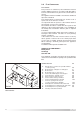
TABLE OF CONTENTS 1. GENERAL INFORMATION PAGE. 3 1.1 1.2 PAGE. 3 PAGE. 4 GENERAL INSTRUCTIONS OVERALL VIEW 2. INSTALLATION 2.1 2.2 2.3 2.4 2.5 2.6 2.7 2.8 2.9 2.10 2.11 2.12 2.13 2.14 2.15 REFERENCE STANDARDS SITING THE APPLIANCE OVERALL DIMENSIONS CLEARANCES MOUNTING THE APPLIANCE ELECTRICAL CONNECTION GAS CONNECTION WATER CONNECTION FLUE CONNECTION CONTROL PANEL DIGITAL DISPLAY AND FAULT CODES REMOVING THE FRONT PANEL ROOM THERMOSTAT CONNECTION ELECTRICAL/SYSTEM DIAGRAMS WATER CIRCUIT DIAGRAM 3.
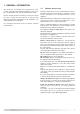
1. GENERAL INFORMATION 1.1 This manual is an integral and essential part of the product. It should be kept with the appliance so that it can be consulted by the user and our authorised personnel. Please carefully read the instructions and notices about the unit contained in this manual, as they provide important information regarding the safe installation, use and maintenance of the product. For operating instructions please consult the separate Users Manual.
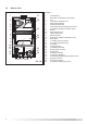
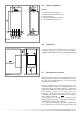
1.2 OVERALL VIEW LEGEND: 1 27 2 26 3 4 5 25 6 7 8 24 23 9 10 11 12 13 14 22 21 20 15 16 17 18 19 FIG. 1.0 4 1. 2. 3. 4. 5. 6. 7. 8. 9. 10. 11. 12. 13. 14. 15. 16. 17. 18. 19. 20. 21. 22. 23. 24. 25. 26. 27.
2. INSTALLATION 2.1 REFERENCE STANDARDS The technical information and instructions provided herein below are intended for the installer / Servicing Technician so that the unit may be installed and serviced correctly and safely. The appliance is only suitable for installation in GB and IE and should be installed in accordance with the rules in force In GB, the installation must be carried out by a CORGI registered installer.
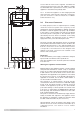
2.3 OVERALL DIMENSIONS LEGEND: A = Central Heating Flow (3/4”) B = Domestic Hot Water Outlet (1/2”) C = Gas Inlet (3/4”) D = Domestic Cold Water Inlet (1/2”) E = Central Heating Return (3/4”) FIG. 2.1 2.4 CLEARANCES In order to allow access to the interior of the boiler for maintenance purposes, the boiler must be installed in compliance with the minimum clearances indicated in FIG. 2.2 2.5 MOUNTING THE APPLIANCE FIG. 2.
secure with the wall screws supplied, assemble the connection kit and secure to the wall. NOTE: It is highly recommended that a spirit level be used to position the appliance to ensure that it is perfectly level. 2.5.2. Position the appliance on the hanging bracket and connect the connection kit to the boiler connections. (see also Sections 2.7 Gas Connections, 2.8 Water Connections & FIG. 2.3). 2.
2.7 GAS CONNECTION The local gas region contractor connects the gas meter to the service pipe. If the gas supply for the boiler serves other appliances ensure that an adequate supply is available both to the boiler and the other appliances when they are in use at the same time. Pipe work must be of an adequate size. Pipes of a smaller size than the boiler inlet connection should not be used. The gas installation should also be in accordance with the relevant standards.
The discharge should terminate facing downward on the exterior of the building in a position where discharging (possibly boiling water & steam) will not create danger or nuisance, but in an easily visible position, and not cause damage to electrical components and wiring. The discharge must not be over an entrance or a window or any other type of public access.
2.9 FLUE CONNECTIONS FLUE SYSTEM The provision for satisfactory flue termination must be made in GB this must be in accordance with BS 5440-1, for IE recommendations are given in the current edition of I.S.813. The appliance must be installed so that the flue terminal is exposed to outside air. The terminal must not discharge into another room or space such as an outhouse or lean-to. It is important that the position of the terminal allows a free passage of air across it at all times.
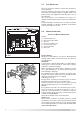
FITTING THE COAXIAL FLUE (HORIZONTAL) (For Telscopic, Vertical Flue and Twin Pipe Instructions see page 12) Ø 60/100 mm CONTENTS: 1X SILICONE O-RING (60mm) 1X ELBOW (90 ) 2X WALL SEALS (INTERNAL & EXTERNAL) 1X ALUMINIUM FLUE PIPE INCLUDING TERMINAL (1 60/100) 2X FLUE CLAMPS 8X SCREWS 2X FOAM SEALS O METRE - Once the boiler has been positioned on the wall, insert the elbow into the socket (F IG 2.7) and rotate to the required position. NOTE: It is possible to rotate the elbow o 360 on its vertical axis.
e.g. X = 508mm + 22mm = 530mm 860 - 530 = 330mm (Length to be cut from the plain end of the flue). Once cut to the required length, ensure that the flue is free from burrs and reassemble the flue. If fitting the flue from inside of the building attach the grey outer wall seal to the flue terminal and push through the flue through the hole, once the wall seal has passed through the hole, pull the flue back until the seal is flush with the wall.
The Vertical flue kits maximum and minimum useable lengths with both flat and pitched roof flashings are indicated in (Figs. 2.14 & 2.15). Before proceeding to fit the flue, ensure that the maximum flue length has not been exceeded and that all elbows and bends have been taken into consideration, the maximum flue length is 5 metres, for each additional 90o elbow 1 metre must be subtracted from the total flue length, and for each 45o 0.
Considerations necessary for twin flue installation; It is most important to avoid any possible condense formation entering the appliance. According to Table 2.1 (Page 17) decide if condensation will form within the flue. If yes, there are two options; 1) Where condense will form but can be negated with insulated flue, install insulated the flue with a fall of 5mm in every metre away from the boiler.
and the air intake must not be sited above the exhaust terminal (refer to FIG. 2.21). The air intake pipe can be run horizontally, however, the terminal and the final 1 metre of flue must be installed with a fall away from the boiler to avoid rain ingress. It is also strongly recommended that the air intake pipe run be constructed of insulated pipe to prevent condense forming on the outside of the tube. The maximum permissible flue length for twin flue is dependent on the type of run used. FIG 2.
TYPE 1 TYPE 4 TYPE 3 TYPE 2 TYPE 5 FIG. 2.20 NOTE: DRAWINGS ARE INDICATIVE OF FLUEING OPTIONS ONLY. AIR INTAKE MUST NOT BE FITTED ABOVE THE EXHAUST AIR INTAKE EXHAUST AIR INTAKE FIG 2.21 NOTE: 16 WHERE 280MM CENTRES CANNOT BE ACHEIVED, THE EXHAUST TERMINAL CAN BE EXTENDED TO PROTRUDE FROM THE WALL BY 300MM.
TABLE 2.
2.10 I E J K C I 2 2 6 6 5 1 4 5 4 1 3 3 FIG. 2.22 FR020A * Warning the flue analysis mode must only be selected by a qualified service engineer.
2.12 1 REMOVING THE FRONT PANEL In order to access the inside of the boiler, it is necessary to unscrew the fastening screws “A” of the control panel located on the lower part of the panel itself. The control panel moves downward and when pulled forward rotates on two lateral hinges. The panel stays in a horizontal position, which allows access to the inner parts of the boiler.
2.14 ELECTRICAL/SYSTEM DIAGRAMS FIG. 2.23 CN203 CN200 CN206 CN304 Q I CN201 CN300 H 1 2 ON 3 4 FUSE B A CN302 5 CN303 6 FUSE 5 6 CN205 ATTENTION When replacing the P.C.B. disconnect the EEPROM key (leave it attached to the control panel) and reconnect to the new PCB.
2.15 WATER CIRCUIT DIAGRAM FIG. 2.24 22 1 21 2 3 20 4 5 6 7 8 19 9 18 17 10 A B 11 C 12 D 14 15 13 E 16 SI016C LEGEND: 1. 2. 3. 4. 5. 6. 7. 8. 9. 10. 11. 12. 13. 14. 15. 16. 17. 18. 19. 20. 21. 22. Fan Heat Exchanger Overheat Thermostat Central Heating Flow NTC Burner Detection Electrode Ignition Electrodes Diverter Valve Low Water Pressure Switch Drain Valve Domestic Hot Water NTC Secondary Heat Exchanger Gas Valve D.H.W. Flow Switch D.H.W.
3. COMMISSIONING 3.1 INITIAL PREPARATION MTS (GB) Limited support the initiative. Within the information pack you will find a copy of the logbook. It is important that this is completed in the presence of your customer, they are shown how to use it, and it is signed by them. Please instruct your customer that they must have their logbook with them whenever they contact a service engineer or us. Preliminary electrical system checks to ensure electrical safety must be carried out by a competent person i.
3.2 INITIAL START-UP T HE CHECKS TO BE RUN BEFORE INITIAL START- UP ARE AS FOLLOWS: E C A I 4 2 2 1 6 6 5 C 5 4 3 1 3 FIG. 2.27 E C D I 1 6 2 2 5 6 4 5 3 4 1 3 FIG. 2.28 3.3 OPERATIONAL ADJUSTMENTS A A 1. Make sure that: - the screw on the automatic air valve has been loosened when the system is full; - If the water pressure in the system is below 1.
3.4 COMBUSTION ANALYSIS FU008A 3.5 PRODUCT OF COMBUSTION DISCHARGE MONITORING The flue connector has two apertures, readings can be taken for the temperature of the combustion by-products and of the combustion air, as well as of the concentrations of O2 and CO2, etc. To access these intakes it is necessary to unscrew the front screw and remove the metal plate with sealing gasket.
E SAFETY SHUTDOWN “E” In the event of a safety cut-off (displayed with the code shown in the table), the boiler will automatically try to reset itself and relight. Should this not be the case, contact an authorised Service Centre for assistance.
3.7 DRAINING THE SYSTEM DRAINING THE HEATING SYSTEM The heating system must be drained as follows: - Turn off the boiler; - Attach a hose pipe and open the drain valve; - Drain the system at the lowest points (where present). When the heating system is unused for an extended period of time, it is recommended that you add antifreeze with an ethylene glycol base to the water in the heating pipe work and radiators if the ambient temperature drops below 0°C during the winter.
4. GAS ADJUSTMENTS TABLE A CATEGORY II2H3+ Lower Wobbe Index (15°C;1013mbar) Nominal Delivery Pressure microGenus II 24 MFFI Main Burner: n. 14 jets (ø) Consumption (15°C; 1013mbar) max - min Consumption (15°C; 1013mbar) max - min Gas Burner Pressure max - min microGenus II 28 MFFI Main Burner: n. 14 jets (ø) Consumption (15°C; 1013mbar) max - min Consumption (15°C; 1013mbar) max - min Gas Burner Pressure max - min microGenus II 31 MFFI Main Burner: n.
4.2 ADJUSTING THE GAS PRESSURES Setting the minimum and the maximum power of the boiler 1. Check that the supply pressure and dynamic working pressure to the gas valve is a minimum of 20 mbar for natural gas. 2. To do this, loosen the screw “A”. Fit the pipe of the pressure gauge to the inlet pressure connection of the gas valve “B” and check for the correct standing pressure, then operate the appliance and check for the correct working pressure.
CN206 CN203 CN200 CN201 1 A B Soft-light Adjustment 2 ON 3 4 5 6 Max Heating Power IMPORTANT! Whenever you disassemble and reassemble the gas connections, always check for leaks using a leak detection fluid. Setting the maximum heating circuit power 7. To set the maximum heating circuit power, turn the On/Off knob to the “ON” position and set the time clock and any external controls to the “ON” position. Turn the knob of the heating thermostat clockwise to maximum. 8.
microGENUS II 24 MFFI NATURAL GAS (G20) kW 10 12 14 16 18 20 22 24 mbar 2.5 3 3.75 4.75 5.75 7 8 10 LIQUID GAS (G30) kW 10 12 14 16 18 20 22 24 mbar 5.5 8 10 12.5 15.5 18.5 22 26 LIQUID GAS (G31) kW 10 12 14 16 18 20 22 24 mbar 7 9 12 15.5 19 24 28 34 microGENUS II 28 MFFI NATURAL GAS (G20) kW 11 13 15 17 19 21 23 25 27 mbar 2 2.75 3.5 4.5 5 6 7 8.5 10 LIQUID GAS (G30) kW 11 13 15 17 19 21 23 25 27 mbar 5 6.5 8.5 10.
FIG. 4.
5. MAINTENANCE It is recommended that the following inspections be carried out on the boiler at least once a year: 1 - Check the seals for the water connections; replace any faulty seals. 2 - Check the gas seals; replace any faulty gas seals. 3 - Visual check of the entire unit. 4 - Visual check of the combustion process or analysis of combustion by-products (see SECTION 3.4) and cleaning of the burner if needed. 5 - If necessary, dismantling and cleaning of the combustion chamber.
6. SERVICING INSTRUCTIONS To ensure efficient safe operation, it is recommended that the boiler is serviced annually by a competent person. Before starting any servicing work, ensure both the gas and electrical supplies to the boiler are isolated and the boiler is cool. Before and after servicing, a combustion analysis should be made via the flue sampling point (please refer to SECTION 3.4 for further details). 2.
6.2.2 Removing the sealed chamber front cover 6.2.3 Removing the side panels 1. Remove the screws “C” (FIG. 6.5); 2. Lift the sealed chamber front cover from the locating pins (FIG. 6.6). 1. Remove the four screws “D” for each side panel (FIG.6.7); 2. Pull the panel away from the boiler at the base, then lift the panel up and remove from the boiler (FIG.6.8). FIG. 6.7 D C C D D FIG. 6.5 D FIG. 6.8 FIG. 6.
6.3 ACCESS TO THE COMBUSTION CHAMBER 6.3.1 Removing the combustion cover 1. Remove the screws “E” (FIG. 6.9); 2. Lift off the combustion cover. FIG. 6.9 Fig. 6.11 6.3.3 Removing the electrodes E E E E Before carrying out this procedure, unscrew and slide the burner forward (see previous section). 1. Remove rubber gasket “G” (FIG. 6.12); 2. To remove the detection electrode disconnect the cable at its connection point close to the P.C.B. (FIG. 6.13); 3. Remove screw “H” (FIG. 6.14); 4.
6.3.4 Removing the main heat exchanger 1. Drain the boiler of water; 2. Remove the side panels (see 6.2.3) 3. Remove the overheat thermostat sensor “I” (FIG. 6.16); 4. Remove the clips “J” (FIG. 6.16); 5. Release the connection nut “K” (FIG. 6.17); 6. Release the connection nut “L” (FIG. 6.18); 7. Pull down the pipe (FIG. 6.19); 4. Pull the exchanger out (FIG. 6.20). FIG. 6.14 H I J J Fig. 6.16 FIG. 6.15 K FIG. 6.
6.3.5 Removing the air pressure switch 1. Disconnect the electrical connections “M” and silicone pipes “N” from their connection points (FIG. 6.21); 2. Remove screws “O” on the top of the sealed chamber (FIG. 6.22); 3. Lift out the air pressure switch (FIG. 6.23); 4. Unscrew to remove the switch from the plate. FIG. 6.21 M Fig. 6.19 N N FIG. 6.22 Fig. 6.20 O O FIG. 6.
6.3.6 Removing the fan 6.4 ACCESS TO THE GAS VALVE 1. Disconnect electrical connections “P” and silicone pipe “Q” (FIG.6.24); 2. Remove screw “R” and remove the fan collar clamp “R” (FIG.6.25); 3. Remove screws “S” (FIG.6.26); 4. Remove fan and mounting plate (FIG.6.27). 6.4.1. Removing the spark generator (HONEYWELL Gas Valve) 1. Disconnect ignition leads “T” by pulling upward (FIG. 6.28); 2. Remove the screw “U” (FIG. 6.29); 3. Remove the spark generator by pulling forward from the gas valve (FIG. 6.
6.5 6.4.2 Removing the gas valve (Honeywell) Important! Before removing the gas valve, ensure the gas supply is turned off. 1. Disconnect all the cables from the solenoid and modureg; 2. Remove the spark generator (see previous section); 3. Release the nuts “V” (FIG. 6.31); 4. Remove the screws “W” from the bottom of the gas valve (FIG. 6.32); 5. Remove the gas valve (FIG. 6.33). ACCESS TO THE WATER CIRCUIT Important! Before any component is removed, the boiler must be drained of all water. 6.5.
6.5.2 Removing the pump pressure switch 1. Remove the pump pressure switch electrical connections “Z” (FIG 6.38); 2. Unscrew the pump pressure switch by using a spanner on the nut (FIG 6.39); 3. Remove the pump pressure switch (FIG 6.40). FIG. 6.37 Z FIG. 6.38 FIG. 6.39 FIG. 6.
6.5.3 Removing the safety valve 1. Disconnect the discharge pipe work from below the boiler; 2. Unscrew the fixing screw “A1” (FIG. 6.42) 3. Pull the valve upwards for removal (FIG. 6.43). 6.5.4 Removing the automatic air vent 1. Remove the U-clip “B1” (FIG. 6.44); 2. Remove valve complete with float using a screwdriver (FIG 6.45-FIG 6.46). B1 FIG. 6.44 FIG. 6.41 A1 FIG. 6.45 FIG. 6.42 FIG. 6.46 FIG. 6.
6.5.5 Removing the pump 1. Remove the electrical connection “ C1” (FIG. 6.47); 2. Release the nut “D1” (FIG. 6.48); 3. Remove the retaining clip “E1” from the bottom of the boiler (FIG. 6.49); 4. Remove the screw “F1” (FIG. 6.50); 5. Remove the U-clip “G1” and remove the pressure gauge connection (FIG. 6.51); 6. Remove the U-clip “H1” and remove the automatic air vent (FIG. 6.52); 7. Remove the pump. F1 FIG. 6.50 C1 G1 FIG. 6.47 FIG. 6.51 D1 H1 FIG. 6.48 FIG. 6.52 E1 FIG. 6.
6.5.6 Removing the pressure gauge 6.5.7 Removing the expansion vessel 1. Remove the U-clip “I1” (FIG. 6.53) 2. Lift the pressure gauge from the rear of the control panel using a screwdriver (FIG. 6.54-6.55). 1. Release nut “J1” (FIG. 6.56); 2. Remove back-nut “K1” (FIG. 6.57); 3. Remove the expansion vessel (FIG. 6.58). I1 J1 FIG. 6.53 FIG. 6.56 K1 FIG. 6.54 FIG. 6.57 FIG. 6.55 FIG. 6.
6.5.8 Removing the overheat thermostat 6.5.9 Removing the C.H. temperature probe (N.T.C.) 1. Disconnect the overheat ther mostat electrical connections “L1” (FIG. 6.59); 2. Then remove the thermostat from its mounting by releasing the securing clip (FIG. 6.60-6.61). 1. Pull off the electrical connector and remove the sensor probe. (FIG. 6.62-6.63). L1 FIG. 6.59 FIG. 6.62 FIG. 6.63 FIG. 6.60 FIG. 6.
6.5.10 Removing the D.H.W. temperature sensor (N.T.C.) 1. Pull off the electrical connector and unscrew the sensor probe using a suitable spanner (FIG. 6.64). 6.5.12 Removing the D.H.W. flow switch 1. Unplug the electrical connector “O1” (FIG. 6.66); 2. Remove the D.H.W. flow switch using a screwdriver (FIG. 6.67-6.68). O1 FIG. 6.64 FIG. 6.66 6.5.11 Removing the diverter valve actuator 1. Unplug the electrical connector “M1” (FIG. 6.65); 2.
6.6 ACCESS TO THE CONTROL SYSTEM Important! Isolate the electrical supply to the boiler before accessing the control panel. 6.6.1 Checking the fuses 1. Remove the inspection cover on the reverse of the control panel and unscrew the screws “P1”(FIG. 6.69); 2. Remove the fuses (FIG. 6.70). P1 P1 FIG. 6.69 FIG. 6.
6.6.2 Removing the P.C.B. 1. Isolate electricity; 2. Remove the inspection cover from the reverse of the control panel, unscrew the screws “Q1” (FIG. 6.71); 3. Unplug all electrical connections from the P.C.B (FIG. 6.72); 4. Carefully unplug the EEPROM key “R1” (FIG. 6.73); 5. Remove the screws “S1” (FIG. 6.74); 6. Separate the facia panel from the rear of the control panel ; 7. Remove the main P.C.B., unscrew the screws “T1” (FIG. 6.75); 8. Unscew the display P.C.B.
6.6.3 Removing the time clock 1. Disconnect the electrical connections “U1” from the clock (FIG. 6.78); 2. Remove screws “V1” (FIG. 6.78); 3. Lift the time clock out from the control panel (FIG. 6.79). U1 V1 FIG. 6.78 FIG. 6.
7. FAULT FINDING 7.1 FAULT FINDING GUIDE (FLOW-CHARTS) These fault finding guides are not exhaustive. However, it is possible to detect and correct many defects by using the standard fault finding diagrams described in this chapter, ensure these guides are carried out in the set order.
A IS THE PUMP RUNNING? NO YES POWER TO THE PUMP? YES IS THE LOW WATER PRESSURE SWITCH WORKING CORRECTLY? E02: does not reset NO 1. Check if there is air in the system 2. Check the main circuit flow switch operation 3. Check the pressure on the water gauge and fill system to 1 bar YES Turn the ON/OFF Control Knob B YES Release/replace pump NO 1. Check pump cable 2. Check/replace main P.C.B.
B IS THE FAN RUNNING? NO DOES CODE E33 APPEAR? YES NO Replace the main P.C.B. IGNITION SPARKS ARE GENERATED REGULARLY? NO YES 1. Check the fan cable 2. Replace the fan 3. Replace the main P.C.B. 1. Check/replace ignition electrode 2. Check ignition cable 3. Check/replace the main P.C.B. YES IS THE BURNER ALIGHT? YES 1. Check the power supply of the gas valve. 2. Check for an air pressure signal NO 3. Check the gas pressure on the burner 4. Check the soft-light adjustment 5.
8.
8.1 SHORT SPARES LIST Key no. 2 9 13 17 18 20 21 22 23 26 37 40 50 63 68 69 70 74 75 76 78 80 94 95 97 101 102 103 109 551 ARISTON Part No. Description Expansion vessel O-ring Motor (3- Way valve) Gasket 3/4" Flow group Gasket 1/4" Low water pressure switch Temperature probe (D.H.W.
General Info Name CE Certification Flue Type Energy Performance Heat Input max/min Heat Output max/min Efficiency of Nominal Heat Input Efficiency at 30% of Nominal Heat Input Efficiency at Minum Input SEDBUK Rating Heat Loss to the Casing (∆T=50°C) Flue Heat Loss with Burner Operating Flue Heat Loss with Burner Off kW kW % % % Band % % % 29.4 / 12.2 24.8 / 9.7 84.3 81.6 79.6 D 1.2 5.1 0.4 33.1 / 13.3 28 / 10.5 84.5 80.5 78.7 D 1.1 5.7 0.
General Info Name CE Certification Flue Type Energy Performance Heat Input max/min Heat Output max/min Efficiency of Nominal Heat Input Efficiency at 30% of Nominal Heat Input Efficiency at Minum Input SEDBUK Rating Heat Loss to the Casing (T=50°C) Flue Heat Loss with Burner Operating Flue Heat Loss with Burner Off kW kW % % % Band % % % 37.2 / 15.5 31.1 / 12.1 83.6 81 78.1 D 1.5 5.7 0.4 Emissions Max Discharge of Products of Combustion (G20) Residual Discharge Head Temp.
BENCHMARK COMMISSIONING CHECKLIST
SERVICE INTERVAL RECORD
Merloni TermoSanitari SpA - Italy Commercial subsidiaries: MTS (GB) Limited MTS Building Hughenden Avenue High Wycombe Bucks HP13 5FT MTS Heating Limited Damastown Industrial Park Damastown Avenue Mulhuddart Dublin 15 Telephone: (01494) 755600 Telephone: (01) 810 3723 Fax: (01494) 459775 Fax: (01) 810 3727 Internet: www.mtsgroup.com/uk Internet: www.mtsgroup.com/ie E-mail: info@uk.mtsgroup.com E-mail: info@ie.mtsgroup.