Installation Instructions Type C Boilers G.C.
TABLE OF CONTENTS 1. GENERAL INFORMATION 1.1 GENERAL INSTRUCTIONS 1.2 OVERALL VIEW 2. INSTALLATION 2.1 2.2 2.3 2.4 2.5 2.6 2.7 2.8 2.9 2.10 2.11 2.12 2.13 DELIVERY REFERENCE STANDARDS SITING THE APPLIANCE OVERALL DIMENSIONS CLEARANCES MOUNTING THE APPLIANCE ELECTRICAL CONNECTION GAS CONNECTION WATER CONNECTIONS FLUE CONNECTION ROOM THERMOSTAT CONNECTION ELECTRICAL DIAGRAMS GAS AND WATER CIRCUITS 3. D.H.W. STORAGE CYLINDER 3.1 2 PORT AND 3 PORT VALVE INSTALLATIONS 3.
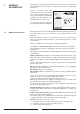
1. GENERAL INFORMATION This manual is an integral and essential part of the product. It should be kept with the appliance so that it can be consulted by the user and our authorised personnel. Please carefully read the instructions and notices about the unit contained in this manual, as they provide important information regarding the safe installation, use and maintenance of the product. User’s Manual For operating instructions please consult the separate User’s Manual. 1.
- Visual check of the combustion process or analysis of combustion byproducts (see section 4.5) and cleaning of the burner if needed. 5 - If called for by point. 3, dismantling and cleaning of the combustion chamber. 6 - If called for by point. 4, dismantling and cleaning of the burner jets. 7 - Visual check of the primary heat exchanger: - check for overheating in the blade assembly; - clean the exhaust fan if needed.
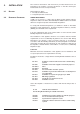
2. INSTALLATION The technical information and instructions provided herein below are intended for the installer / Servicing Technician so that the unit may be installed and serviced correctly and safely. 2.1 DELIVERY There will be two items: 1 - The fully assembled boiler 2 - A separately boxed connection ki 2.2 REFERENCE STANDARDS WATER REGULATIONS In GB it is necessary to comply with the Water Supply (Water Fittings) Regulations 1999, for Scotland, The Water Bylaws 2000, Scotland.
WARNING!! The addition of anything that may interfere with the normal operation of the appliance without express written permission of the manufacturer or his agent could invalidate the warranty. In GB this could also infringe the GAS SAFETY(Installation and Use) REGULATIONS. In the Republic of Ireland the installation and initial start up of the appliance must be carried out by a Competent Person in accordance with the current edition of I.S.
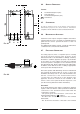
OVERALL DIMENSIONS 400 mm 2.4 LEGEND: 60 mm A C E mm 2.5 = Central Heating Flow (3/4”) = Gas Inlet (3/4”) = Central Heating Return (3/4”) = Clearances CLEARANCES 450 mm In order to allow for access to the interior of the boiler for maintenance pur poses, the boiler must be installed in compliance with the minimum clearances indicated in FIG. 2.1 2.6 132 C FIG. 2.1 E Fasten the boiler in place using the template and anchors supplied with the unit.
marked “L”. Note: The diagrams for the electrical system are indicated in section 2.12. Warning, this appliance must be earthed. External wiring must be correctly earthed, polarised and in accordance with relevant regulations / rules. In GB this is the current I.E.E. WIRING REGULATIONS. In IE reference should be made to the current edition of the ETCI rules. This boiler is supplied for connection to a 220 - 240 V~ 50 Hz supply. The supply must be fused at 3 A.
CENTRAL HEATING Detailed recommendations are given in BS 6798:1987 and BS 5449-1:1990, the following notes are given for general guidance. PIPE WORK Copper tubing to BS EN 1057:1996 is recommended for water pipes. Jointing should be either with capillary soldered or compression fittings. Where possible pipes should have a gradient to ensure air is carried naturally to air release points and water flows naturally to drain taps.
2.10 FLUE CONNECTIONS FLUE SYSTEM The provision for satisfactory flue termination must be made as described in BS 5440-1, for IE recommendations I.S.813. The appliance must be installed so that the flue terminal is exposed to outdoor air, consideration must be given to terminal discharges onto a pathway or passageway, check that the combustion discharges will not cause a nuisance and that the terminal will not obstruct the passageway.
In addition, it is also possible to use a split (twin pipe) system by fitting a special adaptor to the flue connector and using the aperture for the air vent intake located on the top part of the combustion chamber. To utilise the air intake it is necessary to: 1. Remove the bottom of the air intake by cutting it with a suitable knife (see FIG. 2.7); 2. Insert the elbow into the air intake until it reaches the lower end. (There is no need to use gaskets or sealing compounds). FIG. 2.7 Ø 80 mm FIG. 2.
Coaxial Systems ø 60/100 28 RFFI Coaxial Systems ø 60/100 21 RFFI Twin Pipe Systems ø 80/80 28 RFFI Twin Pipe Systems ø 80/80 Restrictor ø 46 mm C12 (xx) C32 (xx) C42 (xx) L min = 0.5 m L max = 1 m Exhaust Type Restrictor ø 41 mm C12 (xx) C32 (xx) C42 (xx) L min = 0.5 m L max = 1 m Exhaust Type Restrictor ø 46 mm C12 (xy) C32 (xy) C42 (xy) L max = 25 m 34 m 34 m 34 m 3.0 m 4.5 m 12.5 m 16.0 m C52 (xy) C82 (xy) L max = 22 m 31 m 3.3 m 4.8 m 14.0 m 17.
2.11 ROOM THERMOSTAT CONNECTION To connect a room thermostat and/or time clock, it is necessary to: 1. - Open the control panel as indicated in section 4.3; 2.- Remove screws “A” and remove the inspection cover from the reverse of the control panel; 3. - For the room-thermostat connect the thermostat switching wires to the position 5 and 6 and remove the wire link (for three-wire thermostats connect the neutral to terminal N); 4.
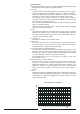
2.12 ELECTRICAL DIAGRAM LEGEND: A11 - Overheat Thermostat A12 - Spark Generator/Gas Valve Supply A13 - Detection Electrode A - On/Off Switch B - On/Off L.E.D. C - Heating Switch D - Heating L.E.D. E - Reset Button F - Ignition Failure (Lockout) L.E.D.
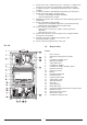
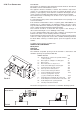
FIG. 2.13 2.13 GAS AND WATER CIRCUITS LEGEND: FIG. 2.14 15 Fan Main heat exchanger Overheat thermostat Burner Ignition electrodes Detection electrode Regulation thermostat Frost thermostat Gas valve Pump pressure switch Safety valve (3 bar) Boiler drain valve Automatic by-pass Pressure gauge Circulation pump with automatic air release valve 16. Expansion vessel 17. Air pressure switch 10 14 13 A. Central Heating Flow C. Inlet Gas E. Central Heating Return 11 12 17 1 2 16 3 4 5 6 7 8 9 15 1.
3. D.H.W. STORAGE CYLINDER 3.1 2 PORT AND 3 PORT VALVE INSTALLATIONS The microSYSTEM can be connected to a storage cylinder (both open-vented and unvented) for the production of domestic hot water (D.H.W.). Cylinders of different capacities can be used depending on site requirements (see TABLE 3.1 for a selection of ARISTON unvented cylinders). 2 port valve installation 3 port valve installation FIG. 3.1 FIG. 3.2 FIG. 3.
Wiring to 3 port valve installation using an external 2 channel programmer Type Danfoss FP715 Type Honeywell ST6400C NOTE: When using a 3 port valve installation in conjunction with an unvented cylinder it will be necessary to use a 2 port valve on the cylinder flow connection in addition to the 3- port valve to satisfy Building Regulations. FIG. 3.4 TABLE 3.1 Technical Data C.H.W. Flow/rate m3/h D.H.W. Flow/rate It/h Max Heating Output kW Heat Ioss It.
3.2 DOMESTIC HOT WATER PRIORITY KIT Boiler microSYSTEM 21 RFFI The microSYSTEM is able to be connected to a specially designed kit for the management of D.H.W. production. This kit gives priority to production of D.H.W. unlike traditional systems where the boiler power is split between C.H. and D.H.W. This generally enables a smaller storage cylinder to be chosen as the boiler’s full output will be channelled into the cylinder allowing for a quick heat-up.
If the gas supply for the boiler serves other appliances ensure that an adequate supply is available both to the boiler and the other appliances when they are in use at the same time. Pipe work must be of an adequate size. Pipes less than the 22mm should not be used. Open the gas cock (supplied with the connection kit) to the appliance and check the gas connections on the appliance for leaks.
3 2 5 4 B To dismantle the front casing panel it is necessary to: 1 - Remove the two screws “B”; 2 - Move the front casing panel up and lift forward. 4.4 INITIAL START-UP THE CHECKS TO BE RUN BEFORE INITIAL START-UP ARE AS FOLLOWS: 1. Make sure that: - the screw on the automatic air valve has been loosened when the system is full; - If the water pressure in the system is below 1.
4.5 COMBUSTION ANALYSIS The flue connector has two apertures, readings can be FIG. 4.2 taken for the temperature of the combustion by-products and of the combustion air, as well as of the concentrations of O2 and CO2, etc. . To access these intakes it is necessary to unscrew the front screw and remove the metal plate with sealing gasket.
4.8 DRAINING THE SYSTEM 5. GAS ADJUSTMENTS The heating system must be emptied as follows: - Turn off the boiler; - Attach a hose pipe and open the drain valve; - Empty the system at the lowest points (where present). When the heating system is unused for an extended period of time, it is recommended that you add antifreeze with an ethylene glycol base to the water in the heating lines and radiators if the ambient temperature drops below 0°C during the winter.
VG002Ab FIG. 5.1 6. MAINTENANCE It is recommended that the following inspections be carried out on the boiler at least once a year: 1 - Check the seals for the water connections; replace any faulty seals. 2 - Check the gas seals; replace any faulty gas seals. 3 - Visual check of the entire unit. 4 - Visual check of the combustion process or analysis of combustion byproducts (see section 4.5) and cleaning of the burner if needed. 5 - If called for by point.
6. TECHNICAL INFORMATION 28 RFFI 21 RFFI CE Certification Heat Input Heat Output Efficiency of Nominal Heat Input Efficiency at 30% of Nominal Heat Input Heat Loss to the Casing (∆T=50°C) Flue Heat Loss with Burner Operating Flue Heat Loss with Burner Off Maximum Discharge of Fumes (G20) Residual Discharge Head Consumption at Nominal Capacity(G20) Gas Consumption after 10 Minutes* (15°C, 1013 mbar) (G30-G31) Temp.