
Operation Manual

Heat pump water heater – INSTALLATION
37
4.7 Connecting the external unit
Remove the gas connections plastic cover, screw the flare nuts to connect the outdoor unit with the same method
described for the internal unit.
4.8 Making the vacuum, the connection and check the seal (see fig 11).
Bleeding from the circuit should take place with a vacuum pump and pressure gauge assembly suitable for R134a.
Make sure the vacuum pump is full of oil up to the level indicated by the oil gauge.
a)
loose the caps of the taps of the 2 and 3 way valves (E), and of the service valve ©; verify that the two valves on
the outdoor unit are closed (D);
b)
connect the vacuum pump (B) to the service valve (C) by the attack of low pressure gauge (A);
c)
After opened the valves of the vacuum pump (B), start it and let it run. Create a vacuum for about 20 / 25
minutes;
d)
verify that the low pressure gauge (A) indicates a pressure of 1 bar-(or -76 cm Hg);
e)
close the valves of the pump and shut off (B). Verify that the gauge needle does not move for about 5 minutes.
If the needle moves, there are air leaks in the system, then you must check all the tightening and execution of
flare at this point repeat the procedure from step c;
f)
Disconnect the vacuum pump, (if you want to add refrigerant gas see the next paragraph);
g)
completely open the taps on 2 and 3 way valves (D);
h)
Screw in the cap on the service outlet © and valves (E);
i)
after having tightened the plugs, make sure there are no gas leaks with the appropriate detector.
CAUTION: Always protect hoses and cables to prevent their being damaged, as once damaged can cause gas leaks
(personal injury from frostbite).
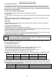
4.9 Charge of the refrigerant gas (Fig. 11)
The product can be installed with refrigerant connection between internal and external unit up to 8 m. The
warranty does not cover installation with refrigerant connection longer than 8 m. The declared performances
are referred to refrigerant connection pipes of 6 m; different types of installation may lead to different values
of performance.
In case you are adding R134a gas in the circuit, will be needed:
- R134a refrigerant tank. In this case it is necessary a charge attack 1/2 UNF 20 threads per inch and corresponding
seal;
- Electronic scale for refrigerant charging with sensitivity 10g.
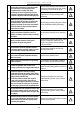
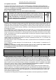
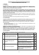
Dur
ing installation
Already installed
Through the installer menu activate the C2 (Charge), you
have 30 minutes to perform the charge with the circuit in
low pressure.
a)
Carry out the procedure of paragraph 4
.8
“
create a
vacuum and check the seal” until the passage “f”;
b)
Connect the manometer on the low pressure service valve
, and connect the refrigerant cylinder to the center tap of
the the manometer. Open the container of the refrigerant
then open the main valve cap pressure gauge and adjust
the needle valve until you hear the coolant leak, and
release the pin and close the valve of the the pipe;
c)
Keep under control the weight of the refrigerant tank
through the electronic scale;
d)
Open the ball valve and to flow the refrigerant gradually;
e)
After reaching the mass of gas to be loaded close the tap;
f) Remove the manometer and charging hose from the
valve;
g)
Fully open taps 2 and 3 way valves (D), turn the product in
heat pump mode with the detector and check for leaks of
refrigerant;
h)
Remove the container from the manifold and replace all
the plugs (E).
a)
Connect the manometer on
the low pressure service
valve, and connect the refrigerant cylinder to the center
tap of the the manometer. Open the container of the
refrigerant then open the main valve cap pressure gauge
and adjust the needle valve until you hear the coolant
leak, and release the pin and close the valve of the the
pipe;
b) Keep under control the weight of the refrigerant tank
through the electronic scale;
c) Open the ball valve and to flow the refrigerant gradually;
d) After reaching the mass of gas to be loaded close the tap;
e) Remove the manometer and charging hose from the
valve;
f) with the detector and check for leaks of refrigerant;
g) Remove the container from the manifold and replace all
the plugs (E).
h) Once finished the time for the “Charge”, verify proper
product functioning.