Istruzioni per l’uso PIANO Sommario IT Italiano, 1 NL Nederlands, 34 GB English, 12 ES Español, 45 FR Français, 22 Installazione, 2-5 Posizionamento Collegamento elettrico Collegamento gas Targhetta caratteristiche Caretteristiche dei bruciatori ed ugelli Descrizione dell’apparecchio, 6 Vista d’insieme Avvio e utilizzo, 7 Consigli pratici per l’uso dei bruciatori Consigli pratici per l’uso delle piastre elettriche Precauzioni e consigli, 8 PF 64/HA PF 640 E/HA PF 640 ES/HA PF 640 EST/HA PF 640 P/HA
Installazione ! È importante conservare questo libretto per poterlo consultare in ogni momento. In caso di vendita, di cessione o di trasloco, assicurarsi che resti insieme all’apparecchio per informare il nuovo proprietario sul funzionamento e sui relativi avvertimenti. ! Leggere attentamente le istruzioni: ci sono importanti informazioni sull’installazione, sull’uso e sulla sicurezza. permettere l’evacuazione dal basso delle eventuali fughe di gas.
Avanti Posizione gancio per top H=40mm Allacciamento del cavo di alimentazione alla rete Montare sul cavo una spina normalizzata per il carico indicato nella targhetta caratteristiche. In caso di collegamento diretto alla rete è necessario interporre tra l’apparecchio e la rete un interruttore onnipolare con apertura minima fra i contatti di 3 mm dimensionato al carico e rispondente alle norme in vigore (il filo di terra non deve essere interrotto dall’interruttore).
IT Sulla rampa di alimentazione dell’apparecchio è presente L” orientabile, la cui tenuta è assicurata da un raccordo a “L una guarnizione. Nel caso risulti necessario ruotare il raccordo sostituire tassativamente la guarnizione di tenuta (in dotazione con l’apparecchio). Il raccordo di entrata del gas all’apparecchio è filettato 1/2 gas maschio cilindrico.
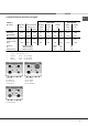
Caratteristiche dei bruciatori ed ugelli IT Tabella 1 Gas liquido Bruciatore Diametro (mm) Potenza termica kW (p.c.s.*) By-Pass 1/100 ugello 1/100 Gas naturale portata* g/h ugello 1/100 Nomin. Ridot.
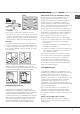
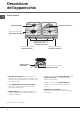
Descrizione dell’apparecchio IT Vista d’insieme PIASTRA ELETTRICA * BRUCIATORI GAS Griglie di appoggio per RECIPIENTI DI COTTURA Manopole di comando dei BRUCIATORI GAS e della PIASTRA ELETTRICA * Pulsante di accensione dei BRUCIATORI GAS * DISPOSITIVO DI SICUREZZA * • PIASTRE ELETTRICHE possono essere di vari diametri e potenze diverse: "normali" o "rapide", quest' ultime si riconoscono dalle altre per la presenza di un bollo rosso al centro.
Avvio e utilizzo ! Su ciascuna manopola è indicata la posizione del bruciatore gas corrispondente. Bruciatori gas Il bruciatore prescelto può essere regolato dalla manopola corrispondente come segue: • Spento Massimo Minimo Per accendere uno dei bruciatori, avvicinare allo stesso una fiamma o un accenditore, premere a fondo e ruotare la manopola corrispondente in senso antiorario fino alla posizione di massima potenza.
Precauzioni e consigli IT ! L’apparecchio è stato progettato e costruito in conformità alle norme internazionali di sicurezza. Queste avvertenze sono fornite per ragioni di sicurezza e devono essere lette attentamente. Sicurezza generale • Questo apparecchio riguarda un apparecchio da incasso di classe 3. • Gli apparecchi gas necessitano, per un corretto funzionamento, di un regolare ricambio d’aria.
Manutenzione e cura Escludere la corrente elettrica Manutenzione rubinetti gas Prima di ogni operazione isolare l’apparecchio dalla rete di alimentazione elettrica. Con il tempo può verificarsi il caso di un rubinetto che si blocchi o presenti difficoltà nella rotazione, pertanto sarà necessario provvedere alla sostituzione del rubinetto stesso.
Anomalie e rimedi IT Può accadere che l'apparecchio non funzioni. Prima di telefonare all'Assistenza, controllare che non si tratti di un problema facilmente risolvibile aiutandosi con il seguente elenco. Anomalie Possibili cause / Soluzione: Il bruciatore non si accende o la fiamma non è uniforme. • Sono ostruiti i fori di uscita del gas del bruciatore. • Sono montate correttamente tutte le parti mobili che compongono il bruciatore. • Ci sono correnti d'aria nelle vicinanze del piano.
Assistenza Prima di contattare l’Assistenza: IT • Verificare se l’anomalia può essere risolta autonomamente (vedi Anomalie e Rimedi); • Riavviare il programma per controllare se l’inconveniente è stato ovviato; • In caso negativo, contattare il Servizio Assistenza Tecnico Autorizzato. ! Non ricorrere mai a tecnici non autorizzati. Comunicare: • Il tipo di anomalia; • Il modello della macchina (Mod.
Operating Instructions HOB Contents GB IT Italiano, 1 NL Nederlands, 34 GB English, 12 ES Español, 45 FR Français, 22 Installation, 13-16 Positioning Electrical connection Gas connection Data plate Burner and nozzle specifications Description of the appliance, 17 Overall view Start-up and use, 18 Practical advice on using the burners Practical advice on using the electric hotplates Precautions and tips, 19 PF 64/HA PF 640 E/HA PF 640 ES/HA PF 640 EST/HA PF 640 P/HA PF631 E/HA PF 631 ES/HA PF 631 P
Installation ! Before operating your new appliance please read this instruction booklet carefully. It contains important information for safe use, installation and care of the appliance. also be equipped with vents to allow gas to escape in the event of a leak. As a result LPG cylinders, whether partially or completely full, must not be installed or stored in rooms or storage areas that are below ground level (cellars, etc.).
Front GB Hooking position for top H=40 mm Connecting the supply cable to the mains Back ! Use the hooks contained in the “accessory pack” • Where the hob is not installed over a built-in oven, a wooden panel must be installed as insulation. This must be placed at a minimum distance of 20 mm from the lower part of the hob. Ventilation To ensure adequate ventilation, the back panel of the cabinet must be removed.
There is an adjustable L-shaped pipe fitting on the appliance supply ramp and this is fitted with a seal in order to prevent leaks. The seal must always be replaced after rotating the pipe fitting (seal provided with appliance). The gas supply pipe fitting is a threaded 1/2 gas cylindrical male attachment. Connecting a flexible jointless stainless steel pipe to a threaded attachment The gas supply pipe fitting is a threaded 1/2 gas cylindrical male attachment.
GB Burner and nozzle specifications Table 1 Liquid Gas Burner Diameter (mm) Thermal power kW (p.c.s.*) By-Pass 1/100 Nozzle 1/100 Natural Gas Flow* g/h Nozzle 1/100 Nomin. Ridot.
Description of the appliance Overall view GB ELECTRIC HOTPLATE * GAS BURNERS Support Grid for COOKWARE Control Knobs for GAS BURNERS and ELECTRIC HOTPLATES Ignition Button for GAS BURNERS * SAFETY DEVICES * • ELECTRIC HOTPLATES may have different diameters and operate at different power levels. These power levels may be “normal” or “rapid” (the latter may be distinguished from the others by a red spot in the middle of the hotplate).
Start-up and use GB ! The position of the corresponding gas burner or electric hotplate* is shown on every knob. Gas burners Each burner can be adjusted to one of the following settings using the corresponding control knob: • Off Maximum Minimum To turn on one of the burners, place a lighted match or lighter near the burner, press the knob all the way in and turn it anti-clockwise to the "High" setting.
Precautions and tips ! This appliance has been designed and manufactured in compliance with international safety standards. The following warnings are provided for safety reasons and must be read carefully. General safety • This is a class 3 built-in appliance. • Gas appliances require regular air exchange to maintain efficient operation. When installing the hob, follow the instructions provided in the paragraph on “Positioning” the appliance.
Maintenance and care GB Switching the appliance off Gas tap maintenance Disconnect your appliance from the electricity supply before carrying out any work on it. Over time, the taps may become jammed or difficult to turn. If this happens, the tap must be replaced. Cleaning the appliance ! This procedure must be performed by a qualified technician authorised by the manufacturer.
Troubleshooting It may happen that the appliance does not function properly or at all. Before calling the service centre for assistance, check if anything can be done. First, check to see that there are no interruptions in the gas and electrical supplies, and, in particular, that the gas valves for the mains are open. GB Problem Possible causes/Solution The burner does not light or the flame is not even around the burner. • The gas holes on the burner are clogged.
Mode d’emploi TABLE DE CUISSON Sommaire FR BE IT Italiano, 1 GB English, 12 LU NL NL Nederlands, 34 ES Español, 45 FR Français, 22 Installation, 23-28 Positionnement Raccordement électrique Raccordement gaz Plaquette signalétique Caractéristiques des brûleurs et des injecteurs Description de l’appareil, 29 Vue d’ensemble Mise en marche et utilisation, 30 Conseils pratiques pour l’utilisation des brûleurs Conseils pratiques pour l’utilisation des plaques électriques Précautions et conseils, 31 PF
Installation ! Conservez ce mode d’emploi pour pouvoir le consulter à tout moment. En cas de vente, de cession ou de déménagement, veillez à ce qu’il suive l’appareil pour informer le nouveau propriétaire sur son fonctionnement et lui fournir les conseils correspondants.
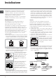
600mm min. 600mm min. BE 700mm min. FR En cas d’installation de la table de cuisson sous un élément haut, ce dernier devra être monté à au moins 700 mm de distance du plan (voir figure). . 560 mm 45 m m. LU NL • La découpe du meuble doit avoir les dimensions indiquées par la figure. Des crochets de fixation sont prévus pour fixer la table sur des plans de 20 à 40 mm d’épaisseur. Pour bien fixer la table, utilisez tous les crochets fournis.
! Il doit être contrôlé périodiquement et ne peut être remplacé que par un technicien agréé (voir Assistance). ! Nous déclinons toute responsabilité en cas de non respect des normes énumérées ci-dessus. Raccordement gaz • Pour la France Raccorder l’appareil à la bouteille ou à la canalisation du gaz conformément aux normes en vigueur, uniquement après avoir vérifié que l’appareil est bien réglé pour le type de gaz d’alimentation utilisé.
FR BE LU NL • Regolazione minimi (pour la France e la Belgique) 1. Placez le robinet sur la position de minima; 2. Déposez la manette et tournez la vis de réglage positionnée à l’intérieur ou sur le côté de la tige du robinet jusqu’à ce que vous obteniez une petite flamme régulière; 3. Une fois obtenu le débit minimal souhaité, allumez le brûleur et tournez brusquement la manette de la position de ralenti à la position d’ouverture maximale et vice versa à plusieurs reprises.
Caractéristiques des brûleurs et des injecteurs Tableau 1 (Pour la France et la Belgique) Brûleur Diamêtre (mm) FR Gaz liquidés Puissance thermique kW (p.c.s.*) By-pass Injecteur 1/100 1/100 Gaz natural Débit* (g/h) Air propané (2) Injecteur 1/100 Débit* (l/h) Injecteur Débit* 1/100 l/h LU (mm) Nomin. Rédu.
FR Pour la Hollande Brûleur Diamètre (mm) BE LU NL Gaz Naturels Puissance thermique kW (p.c.s. *) Nominal Réduit Injecteur 1/100 (mm) Débit* (l/h) G 25 Rapide (R) 100 3,00 0,70 116 332 Semi Rapide (S) 75 1,90 0,40 106 210 Auxiliaire (A) 55 1,00 0,40 79 111 Triple Couronne (TC) 100 2,50 0,80 124 277 Pression de alimentation * ** *** Nominale (mbar) Minimum (mbar) Maximum (mbar) A 15°C et 1013 mbar-gaz sec Propane P.C.S. = 50,37 MJ/kg Butane P.C.S.
Description de l’appareil Vue d’ensemble FR BE LU PLAQUE ÉLECTRIQUE * BRÛLEURS À GAZ NL Grilles support de CASSEROLES Manettes de commande des BRÛLEURS GAZ et de la PLAQUE ÉLECTRIQUE * Bougie d’allumage des BRÛLEURS GAZ * DISPOSITIF DE SÉCURITÉ * • PLAQUES ÉLECTRIQUES disponibles dans plusieurs diamètres et puissances : elles peuvent être “normales” ou “rapides”, ces dernières sont repérables à leur point rouge.
Mise en marche et utilisation FR BE LU NL ! La position du brûleur gaz ou de la plaque électrique* correspondante est indiquée sur chaque manette. Brûleurs à gaz Chaque manette permet de régler le brûleur sélectionné comme suit: • Eteint Maximum Minimum Pour allumer un brûleur, approchez une flamme ou un allume-gaz, appuyez à fond sur la manette correspondante et tournez-la dans le sens contraire des aiguilles d'une montre jusqu'à la position: puissance maximum.
Précautions et conseils ! Cet appareil a été conçu et fabriqué conformément aux normes internationales de sécurité. Ces conseils sont fournis pour des raisons de sécurité et doivent être lus attentivement. Sécurité générale • Ce mode d’emploi concerne un appareil à encastrer classe 3. • Pour bien fonctionner, les appareils à gaz ont besoin d’un apport d’air régulier.
Nettoyage et entretien FR BE LU NL Mise hors tension Entretien robinets gaz Avant toute opération de nettoyage ou d’entretien coupez l’alimentation électrique de l’appareil. Il peut arriver qu’au bout d’un certain temps, un robinet se bloque ou tourne difficilement. Il faut alors le remplacer. Nettoyage de l’appareil ! Cette opération doit être effectuée par un technicien agréé par le fabricant.
Anomalies et remèdes Il peut arriver que l’appareil ne fonctionne pas ou ne fonctionne pas très bien. Avant d’appeler le service aprèsvente, voyons ensemble que faire. Vérifiez avant tout s’il n’y a pas de coupure de gaz ou de courant, et si les robinets du gaz en amont de l’appareil sont bien ouverts. FR BE Anomalies Causes / Solutions possibles Le brûleur ne s’allume pas ou la flamme n’est pas uniforme. • les orifices de sortie du gaz ne sont pas par hasard bouchés.
Gebruiksaanwijzing KOOKPLAAT Samenvatting NL Het installeren, 35-39 BE IT Italiano, 1 NL Nederlands, 34 GB English, 12 ES Español, 45 FR Français, 22 Plaatsing Elektrische aansluiting Gasaansluiting Typeplaatje Kenmerken van de branders en de straalpijpjes Beschrijving van het apparaat, 40 Algemeen aanzicht Starten en gebruik, 41 Praktisch advies voor het gebruik van de branders Praktisch advies voor het gebruik van de elektrische kookplaten Voorzorgsmaatregelen en advies, 42 PF 64/HA PF 640 E/HA
Het installeren ! Bewaar dit boekje zorgvuldig voor eventuele verdere raadpleging. Wanneer u het product weggeeft, verkoopt, of wanneer u verhuist, dient u dit boekje bij het apparaat te bewaren zodat alle nodige informatie voorhanden blijft. A ! Lees de gebruiksaanwijzingen zorgvuldig door: er staat belangrijke informatie in over installatie, gebruik en veiligheid.
600mm min. 600mm min. BE 700mm min. NL Als de kookplaat onder een keukenkastje wordt geplaatst, moet deze zich op een afstand van minstens 700 mm van het keukenblad bevinden (zie afbeelding). • De opening van het meubel moet de afmetingen hebben die in de afbeelding zijn aangegeven. De bevestigingsklemmen maken een bevestiging mogelijk van de kookplaat aan een keukenblad van tussen de 20 en 40 mm dik. Voor een goede bevestiging raden wij u aan alle bijgeleverde haken te gebruiken.
! De installateur is verantwoordelijk voor een correcte elektrische aansluiting en het in acht nemen van de veiligheidsnormen. Voor het aansluiten moet u controleren dat: • het stopcontact geaard is en voldoet aan de geldende normen; • het stopcontact in staat is het maximale vermogen van het apparaat te dragen, zoals aangegeven op het typeplaatje; • de spanning zich bevindt tussen de waarden die staan aangegeven op het typeplaatje; • het stopcontact en de stekker overeenkomen.
NL BE kookplaat of op de verpakking), moeten de straalpijpjes van de branders op de volgende wijze worden vervangen: 5. Als de regeling voltooid is moet u de zegels op de bypass schroefjes weer op hun plaats brengen met zegellak of dergelijk materiaal. 1. verwijder de roosters van de kookplaat en schuif de branders uit hun plaats. 2.
Kenmerken van de branders en de straalpijpjes Table 1 (Voor Belgie) Gaspit NL Vloeibaar gas Doorsnee Thermisch vermogen kW (p.c.s.*) (mm) Nomin. Gered. By-pas- Straal. s 1/100 1/100 Natuurlijk gas Bereik* (g/h) Straal.
Beschrijving van het apparaat NL Algemeen aanzicht BE ELEKTRISCHE KOOKPLAAT * GASBRANDERS Roosters voor PANNEN Knoppen voor het regelen van de GASBRANDERS en de ELEKTRISCHE KOOKPLAAT * Ontstekingsknop voor de GASBRANDERS * Controlelampje werking ELEKTRISCHE KOOKPLAAT * VEILIGHEIDSMECHANISME * Bougie voor ontsteking van de GASBRANDERS * • ELEKTRISCHE PLATEN kunnen verschillende diameters en vermogen hebben: “normaal” of “snel”, dit laatste type platen herkent u door de aanwezigheid van een rode stip
Starten en gebruik ! Op iedere knop staat aangegeven waar de gasbrander zich precies bevindt. Gasbranders De gekozen brander kan met de betreffende knop als volgt worden geregeld: • Uit Maximum Minimum Voor het aansteken van één van de gasbranders houdt u er een vlammetje bij of een gasaansteker, drukt u de knop in en draait u hem tegen de klok in tot aan de positie van maximum sterkte.
Voorzorgsmaatregelen en advies NL BE ! Dit apparaat is ontworpen en vervaardigd volgens de geldende internationale veiligheidsvoorschriften. Deze aanwijzingen zijn geschreven voor uw veiligheid en u dient ze derhalve goed door te nemen. Algemene veiligheidsmaatregelen • Dit is een inbouwapparaat van klasse 3. • Gasfornuizen hebben voor een goede werking behoefte aan een regelmatige luchtverversing. Controleer dat bij het installeren aan de vereisten wordt voldaan beschreven in de paragraaf “Plaatsing”.
Onderhoud en verzorging De elektrische stroom afsluiten Sluit altijd eerst de stroom af voordat u tot enige handeling overgaat. gelegen. Spoel en droog het dus na het schoonmaken goed af. Droog watervlekken altijd gelijk af. Onderhoud gaskranen NL BE Schoonmaken van het apparaat Met verloop van tijd kan een kraan stroef worden of vast blijven zitten; in dat geval is het noodzakelijk hem te vervangen.
Storingen en oplossingen NL Het kan gebeuren dat het kookvlak niet (afdoende) functioneert. Voordat u de servicedienst belt dient u te controleren of u het euvel zelf kunt oplossen. Verifieer om te beginnen of er een correcte stroom- en gastoevoer is, en in het bijzonder of de hoofdgasleiding open staat. BE Storingen Mogelijke oorzaken / Oplossing De brander gaat niet aan of de vlam is niet gelijkmatig. • De openingen van de vlamverspreiders niet verstopt zijn.
Manual de instrucciones ENCIMERA Sumario ES IT Italiano, 1 NL Nederlands, 34 GB English, 12 ES Español, 45 FR Français, 22 Instalación, 46-49 Colocación Conexión eléctrica Conexión gas Placa de características Características de los quemadores e inyectores Descripción del aparato, 50 Vista de conjunto Puesta en funcionamiento y uso, 51 Consejos prácticos para el uso de los quemadores Consejos prácticos para el uso de las placas eléctricas Precauciones y consejos, 52 PF 64/HA PF 640 E/HA PF 640 ES
Instalación ! Lea atentamente las instrucciones: contienen importante información sobre la instalación, el uso y la seguridad. Colocación ! Los embalajes no son juguetes para niños y se deben eliminar respetando las normas para la recolección de residuos (ver Precauciones y consejos). ! La instalación se debe realizar siguiendo estas instrucciones y por personal profesionalmente calificado. Una instalación incorrecta puede producir daños a personas, animales o cosas.
Conexión eléctrica Esquema de fijación de los ganchos Posición del gancho para superficies H=20mm Posición del gancho para superficies H=30mm Adelante Las encimeras que poseen cable de alimentación tripolar, se fabrican para funcionar con corriente alterna, a la tensión y frecuencia de alimentación indicadas en la placa de características (ubicada en la parte inferior de la encimera). El conductor de puesta a tierra del cable se distingue por los colores amarillo-verde.
ES En el caso de alimentación con gas líquido, desde botella, utilice reguladores de presión conformes con las Normas Nacionales vigentes. • Regulación de aire principal de los quemadores ! Para un funcionamiento seguro, un adecuado uso de la energía y una mayor duración del aparato, verifique que la presión de alimentación cumpla con los valores indicados en la tabla 1 “Características de los quemadores e inyectores”.
Características de los quemadores e inyectores Tabla 1 ES Gas liquido Quemador Diametro Potencia térmica kW (p.c.s.*) By-Pass 1/100 pico 1/100 Gas natural capacid.* g/h pico 1/100 capacid.* l/h (mm) Nomin. Reduc.
Descripción del aparato ES Vista de conjunto PLACA ELÉCTRICA * QUEMADORES A GAS Parrillas de apoyo para RECIPIENTES DE COCCIÓN Mandos de los QUEMADORES A GAS y de la PLACA ELÉCTRICA * Botón de encendido de los QUEMADORES A GAS * DISPOSITIVO DE SEGURIDAD * • PLACAS ELÉCTRICAS: pueden ser de distintos diámetros y de distintas potencias como por ejemplo: “normales” o “rápidas”, éstas últimas se distinguen de las otras por la presencia de un sello rojo en el centro.
Puesta en funcionamiento y uso ! En cada mando está indicada la posición del quemador a gas correspondiente. Quemadores a gas El quemador elegido se puede regular con el mando correspondiente de la siguiente manera: • Apagado Máximo Mínimo Para encender uno de los mecheros, acercar al mismo una llama o un encendedor, apretar a fondo y girar el botón correspondiente en sentido antihorario hasta la posición de máxima potencia.
Precauciones y consejos ES ! El aparato ha sido proyectado y fabricado en conformidad con las normas internacionales de seguridad. Estas advertencias se suministran por razones de seguridad y deben ser leídas atentamente. Seguridad general • Este aparato se refiere a un aparato empotrable de clase 3. • Para su correcto funcionamiento, los aparatos a gas necesitan un regular cambio de aire.
Mantenimiento y cuidados Cortar la corriente eléctrica Mantenimiento de las llaves de gas Antes de realizar cualquier operación, desconecte el aparato de la red de alimentación eléctrica. Con el tiempo puede suceder que una llave se bloquee o presente dificultad para girar, en esos casos será necesario proceder a la sustitución de dicha llave.
Anomalías y soluciones ES Puede suceder que la encimera no funcione o no funcione bien. Antes de llamar al servicio de asistencia técnica, veamos qué se puede hacer. Antes que nada verifique que no hayan interrupciones en las redes de alimentación de gas y eléctrica, y en particular, que las llaves de gas, aguas arriba del aparato, estén abiertas. Anomalías Posibles causas / Solución El quemador no se enciende o la llama no es uniforme. • Los orificios de salida de gas del quemador están obstruidos.
ES 55
11/2010 - 195061710.