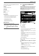
MODEL GWH 2400 ES NG and GWH 2400 ES LP INDOOR MODEL Temperature Modulated with Electronic Ignition Suitable for heating potable water only Not approved for space heating purposes (Intended for variable flow applications) GWH 2400 ES NG - Natural Gas GWH 2400 ES LP - Liquefied Petroleum (LP) Gas 6 720 608 782 US (2007.05) AL Warning: If the information in this manual is not followed exactly, a fire or explosion may result causing property damage, personal injury or death.
Index Index 1 Warning 3 2 2.1 2.2 Appliance details Features GWH 2400 ES Specifications (Technical data) Unpacking the GWH 2400 ES heater General rules to follow for safe operation Dimensions and Minimum installation clearances 4 4 2.3 2.4 2.5 4 5 6 7 3 3.1 3.2 3.3 3.4 3.5 3.6 3.7 3.8 3.9 3.10 3.11 3.
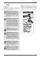
Warning 1 Warning For your safety Do not store or use gasoline or other flammable, combustible or corrosive vapors and liquids in the vicinity of this or any other appliance. FCC: This device complies with Part 15 of the FCC rules. Operation is subject to the following two conditions: (1) This device may not cause harmful interference, and (2) this device must accept any interference received, including interference that may cause undesired operation.
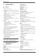
Appliance details 2 Appliance details Maximum input 175,000 Btu/h (51.2 kW) 2.1 Features Efficiency in % Thermal efficiency > 82% Parts • Key Pad interface control Min. Input • High power pre-mix compact burner with low NOx emissions 19,900 Btu/h (5.8 kW) Temperature Control • Modulating Gas Valve with constant gas:air ratio control Selection range: 100°F (38°C) - 140°F (60°C) • Modulating water valve for improved comfort and temperature control.
Appliance details Call Bosch Water Heating through BBT North America for conversion instructions. 2.3 Voltage Before installing the unit, be certain you have the correct heater for your type of Gas: Propane or Natural Gas. Identification labels are found on the shipping box, and on the rating plate which is located on the right side panel of the cover. 120 V AC (60 Hz) nominal Amperage Idle - 40 mA Operation - ≤ 2.
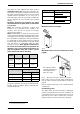
Appliance details To remove front cover B Loosen the two Philips head screws located on bottom rear of cover (see Fig. 3). Fig. 3 Loosen the two screws B Lift front cover panel upward and remove. Fig. 4 Removing the front cover To remove combustion cover (service only) B Open the four clips and remove the combustion cover see Fig. 5. Fig. 5 6 Remove the combustion cover 2.4 General rules to follow for safe operation B 1. You must follow these instructions when you install your heater.
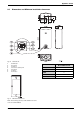
Appliance details 2.5 Fig. 6 1 2 3 4 5 6 7 Dimensions and Minimum installation clearances Dimensions On/Off button Reset button Program key Power ON or stand-by LED LCD display Up button Down button Model GWH 2400 ES TOP (A) 12” FRONT (B) 1” BACK 0” SIDES 1” FLOOR (C) 12” Table 1 Minimum clearances Fig. 7 Minimum clearances Note: For servicing access, a 2ft clearance to front cover is recommended.
Installation instructions 3 Installation instructions 3.1 Tools required for installation 3.3 • Philips head screwdriver Venting Warning: Do not reduce the vent (exhaust and combustion) pipe sizes and do not common vent with any other vented appliance or stove.
Installation instructions vent length for each additional 90° elbow used (a maximum of three 90° elbows are permitted in the total exhaust vent length), or subtract 1.25 feet for every 45° elbow used. Horizontal sections of vent must pitch upwards towards termination ¼" for every foot of horizontal length, to prevent the pooling of condensate, and be supported at 4 foot intervals with overhead hangers.
Installation instructions Recommended exhaust vent terminator position Fig. 10 Ref.
Installation instructions Venting configuration examples Fig. 13 Above the roof clearance requirements from rain cap (combustion air piping not shown) Fig. 11 Horizontal side wall venting installation (combustion air piping not shown) Important: Note: Pitch horizontal runs down toward the heater, except horizontal run between last elbow and termination which must slope down to termination 1/4" per foot.
Installation instructions 3.3.2 Room sealed installation (TWIN PIPE SYSTEM) Condensate drain requirements A condensate drain must be installed under the following conditions: • All vertical terminating vent installations • Horizontal terminating vent installations where the total equivalent exhaust vent length is greater than 10 feet. See table 17, page 33. Installing this water heater as a room sealed (TWIN PIPE SYSTEM) is the recommended method.
Installation instructions Warning: Approved terminators must be used for inlet and exhaust vent systems to prevent rain from entering the appliance, failure to do so may result in damage to the appliance. This failure is not covered under the manufacturer’s warranty. first one, reduce 1.25 ft for each 45° elbow. A maximum of three 90-degree elbows are permitted. Determining installation adjustment The GWH 2400 ES comes factory set to accomodate most common venting arrangements.
Installation instructions 3.3.3 Vent connections B Attach the flue gas exhaust accessory (8 705 504 151) to the top of the unit (position 1) using the 4 screws and gasket provided. Fully insert stainless steel vent pipe 1.5” minimum into the accessory and tighten the clamp (position 2). Fig. 20 B Attach the combustion air inlet accessory (8 705 504 154) to the top of the unit (position 3) using the 3 screws and gasket provided, and install air intake pipe over the accessory.
Installation instructions signage installed in accordance with the provisions of 248 CMR 5.08(2)(a)1 through 4. (b) EXEMPTIONS: The following equipment is exempt from 248 CMR 5.08(2)(a)1 through 4: 1. The equipment listed in Chapter 10 entitled "Equipment Not Required To Be Vented" in the most current edition of NFPA 54 as adopted by the Board; and 2.
Installation instructions consume air in the space. Always follow local codes if they are more stringent. This Installation Manual specifies the minimum exhaust vent length (Fig. 8, page 9) and the amount of combustion air required for this unit. When all requirements are followed, the unit will operate properly and safely. However, there may still be a risk of freezing due to negative draft if the other combustion appliances in the building are not supplied with sufficient combustion air.
Installation instructions Warning: Do not install this appliance on a carpeted wall. The heater must be mounted on a wall using appropriate anchoring materials. If wall is sheathed with plaster or drywall, it is recommended that two support boards, either 1”x4” or 1/2" (minimum) plywood first be attached across a pair of studs, see Fig. 22. B Secure the wall mounting bracket provided with the heater to the wall surface. The heater must be kept level on the wall surface (see Fig. 23).
Installation instructions B The minimum internal diameter required for any appliance connector is ¾”. B Undersized permitted. flexible appliance connectors not B National Fuel Gas Code requires that a sediment trap (drip leg) be installed on gas appliances not so equipped. The drip leg must be accessible and not subject to freezing conditions. Install in accordance with the recommendations of the serving gas supplier, see Fig. 25. Gas piping Inlet gas particle screen (included) Fig.
Installation instructions FOR NATURAL GAS Maximum Capacity of pipe in Cubic Feet of Gas per Hour for Gas Pressure of 0.5 Psig or less and a Pressure drop of 0.3” in Water Column (0.75mbar).(Based on a 0.60 Specific Gravity Gas) Btu numbers given in thousands. Follow boxed numbers for piping just one GWH 2400 ES (example: ¾” B.I. Natural Gas pipe for 10 ft (3.0m). will handle 278,000 btu’s (81.5 kWh). For multiple appliances combine the total maximum btu input load and then refer to applicable chart below.
Installation instructions 3.9 Water connections Warning: This heater is not approved for preheated water applications. See chapter 3.11 for approved recirculating application. B When facing the heater, the ¾” cold connection is on the bottom right and the hot connection is on the bottom left. Centrally locating the water heater is recommended to keep hot water distribution times even throughout the structure. 3.
Installation instructions Connecting the pressure relief valve (PRV) A listed pressure relief valve supplied with the heater must be installed at the time of installation. No valve is to be placed between the PRV and the heater. No reducing coupling or other restriction may be installed in the discharge line. The discharge line must be a minimum of 4” above a drain and installed such that it allows complete drainage of both the PRV and the line.
Installation instructions B Record lowest operating gas pressure reading in table 11. 3.12 Measuring gas pressure Confirm gas pressure upon installation. Connecting manometer B Shut off gas supply at installer supplied shutoff valve for this water heater. Gas pressures lower than 4" W.C. for Natural Gas or 9" W.C. for LPG will result in insufficient degree rise to the hot water being used, reduced hot water volume, possible error code faults and must be corrected. See Gas Connections, chapter 3.
Electrical connections 4 Electrical connections 4.1 Electrical power supply Warning: For safety reasons, disconnect the power supply cord to the heater before any service or testing is performed. Warning: This heater must be electrically grounded in accordance with the most recent edition of the National Electrical Code. NFPA 70. In Canada, all electrical wiring to the heater should be in accordance with local codes and the Canadian Electrical Code, CSA C22.1 Part 1.
Operation instructions 5 Operation instructions Fig. 36 1 2 3 4 5 6 7 5.1 On/Off button Reset button Program Key LCD display Up button Down button LED - Power On indicator or Stand-by LCD Display functions Warning: Do not use any cleaning or corrosive agent to clean the window. Fig. 40 Lock indicator Fig. 41 Flame indicator Fig. 37 Power bar indicator Fig. 42 Remote control Fig. 38 Temperature indicator Fig.
Operation instructions 5.2 For your safety read before operating your water heater Warning: If you do not follow these instructions exactly, a fire or explosion may result causing property damage, personal injury or loss of life. 5.4 Temperature selection To select output water temperature: B Press buttons temperature. or in order to reach desired A. This appliance is equipped with electronic ignition for lighting the main burner. When turning the heater on, follow these instructions exactly. B.
Operation instructions 5.5 Use of optional remote control accessory (part no. TSTAT2) Fig. 48 Reset button If the problem persists, contact your installer. 5.8 Program button can be used on the appliance and in the remote control. Fig. 45 Remote control The wireless remote control accessory (Fig. 70, component 13) and the temperature selector buttons on the front of the water heater operate identically. Contact your distributor to order the remote control accessory.
Maintenance and service 6 Maintenance and service Warning: Always turn off the electrical power supply, turn off the manual gas shut off valve and turn off the water shut off valves whenever servicing. Caution: B Check and clean the complete water heating system once a year. Inlet water filter • Verify the inlet filter screen is clean and undamaged. The inlet water filter is located inside the cold water inlet fitting on the right side of the appliance (See Fig. 51, page 27).
Maintenance and service such as anti-freeze is not permitted as they may cause damage to the water heater's internal components. 1. Press ON/OFF switch on the water heater to turn OFF the heater and unplug power supply cord. The display should be blank. 2. Shut off gas supply to heater. 3. Shut off the water supply to the water heater using installer supplied shutoff valve. 4. Open hot water taps to drain the plumbing system.
Maintenance and service adjusting CO2 until pressure is at or above these levels, but not to exceed 14” WC. P1 CO2 Reading: A. Once Gas Pressure is adequate C. Adjusting CO2: B Press ON/OFF button to turn off the heater. Note: P1 adjustment will change the P2 reading. Confirm the P1 value BEFORE adjusting the P2 level. B Remove brass flat head screw on the exhaust collar as seen in Fig. 53. B Insert CO2 analyzer probe into the measuring port.
Maintenance and service CO2 range (%) Max. CO level Nat. Gas max. input P1 6.9 % - 7.5 % < 250 ppm min. input P2 2.3 % - 2.6 % < 55 ppm LP Gas max. input P1 8.1 % - 8.7 % < 250 ppm min. input P2 2.5 % - 2.8 % < 55 ppm * Values above are for climate controlled conditions. Inputs such as gas pressure, heating value of the gas, humidity and temperature of combustion air all impact CO and CO2 values. Changes in these inputs can result in different CO and CO2 values on the same appliance.
Maintenance and service 6.5 Program values This section describes details on programming the appliance. For most applications the factory default values will robust and stable operation. Only adjust the factory settings if the installation requires changes as indicated in the appropriate section of this manual. Refer to chapter 6.6 Control board diagnostics (page 32) regarding how to access these P-modes. Caution: Misadjusted program values can lead to appliance malfunction, errors, and service calls.
Maintenance and service 6.6 Control board diagnostics 1. Turn on/off switch on water heater to off (O) position. 2. Press and hold the program ( ) button while turning the on/off switch to the on (I) position. The display will cycle through a startup procedure including the software version. 3. Release the ' ' button when '188' appears on the display. The display should read 'P2' when the program button is released. If not, repeat process.
Maintenance and service 6.7 Fan speed adjustment Example Installation adjustment: Flue pipe length setting for minimum power - P2. Exhaust After installing the GWH 2400 ES, the minimum power fan speed must be selected to compensate for variation in vent pipe length. Straight section length (feet) 22 x 1 = 22 90° elbows (qty) 1 x 2.5 = 2.5 45° elbows (qty) 0 x 1.
Maintenance and service To select fan speed: B Press ON/OFF button into OFF. B Press and hold "Program" button and press ON/OFF button to turn appliance ON. Fig. 57 B As soon as '188' is displayed, release "Program" button , and the display should read P2. B Press or to choose the fan speed suitable with your installation, see Table 19. B Press and hold (± 5 sec.) “Program” button until the display flashes, then the selected value is memorized.
Troubleshooting 7 Troubleshooting Warning: If you are unable to perform the tasks listed below, or need additional assistance please contact your original installer or licensed gas technician. 7.1 Introduction Many of the questions customers ask regarding operation of this unit can be answered by following the troubleshooting steps as outlined below. Visit our web site at www.boschhotwater.com for more detailed troubleshooting and service bulletins.
Troubleshooting the heater. Wait 10 minutes and check all taps for water flow. There should be no water flowing. Any continuous flow of water, small or large, indicates a crossover and must be corrected. Consult a professional plumber for help in correcting a crossover. Failing single lever faucets and mixing valves are common causes of plumbing crossovers. 8. Ensure the outlet temperature sensor is making contact and firmly mounted on the hot water pipe. 7.5 Low water flow/pressure 1.
Troubleshooting out of adjustment. This will result in unstable burner flames and noise. Ensure gas pressure is in accordance with specifications in section 3.12, page 21 Measuring Gas Pressure. A gas pressure reading is needed to proceed further. Contact your original installer or a local certified gas technician to obtain this reading. 6. Verify proper CO2 readings per chapter 6.4, page 28. CO2 adjustments must be done by a certified gas technician with a calibrated combustion gas analyzer.
Problem solving 8 Problem solving 8.1 Error code diagnostics i To remove error code from the display, press the reset button. Display Cause Solution Fault in the flue gas limiter. 1. Check continuity of the flue gas limiter (see Fig. 63, page 46). Go to steps two and three to determine air box temperature sensor fault and replace it. 2. Check for flue gas leakage around the top and bottom seals of heat exchanger as well as the viewing window. 3.
Problem solving Display (Flashing) (Flashing) Cause Solution Outlet temperature sensor not sensing expected output temperature. 1. Check that the sensor is firmly attached to the hot water pipe (see Fig. 69, page 52). 2. Clean inlet filter screen and clear any debris out of shower heads, faucet aerators and whole house filters. 3. Check venting specifications are met. Long vent lengths, venting with more than three elbows, blocked vent or combination venting may cause this failure. 4.
Problem solving Display Cause Solution Internal hardware/software failure. 1. Disconnect power supply cord and check the two wire and ground connections on control board as well as ground connection on heater chassis. 2. Pushing the wrong combination of buttons on the control unit can create confusion among the microprocessors inside. In this case, the error code should not happen more than once or twice. Turn off the water heater. Turn water heater back on and try resetting error code.
Problem solving Display Cause Solution No flame ionization detected with water flow. 1. Verify that all manual gas shut off valves are open. 2. Check gas type, see Fig. 2, page 5. 3. Reset error code and open a water tap to cycle the heater in an effort to purge air on new installations. Cycling hot water tap on and off multiple times may be necessary. If heater still faults with EA error code, have a licensed gas technician properly purge air out of the gas line leading to the water heater. 4.
Electrical diagram 9 Electrical diagram Fig.
Sensor resistance charts 10 Sensor resistance charts 110 222 2 17 2 12 207 202 19 7 19 2 18 7 18 2 177 172 16 7 16 2 157 152 14 7 14 2 13 7 13 2 12 7 12 2 117 112 10 7 10 2 97 92 87 82 77 72 67 62 57 52 47 42 37 32 10 5 10 0 95 90 85 80 75 70 65 60 55 50 Temp ºC Temp ºF Outlet temperature sensor characteristics 45 40 35 30 25 20 15 10 5 0 0 1 2 3 4 5 6 7 8 9 10 11 12 13 14 15 16 17 18 19 20 21 22 23 24 25 26 27 28 29 30 31 32 33 34 35 36 37 Resistance (Kohm) Fig.
Sensor resistance charts 155 302 297 292 287 282 277 272 267 262 257 252 247 242 237 232 227 222 2 17 2 12 207 202 19 7 19 2 18 7 18 2 17 7 17 2 16 7 16 2 15 7 15 2 14 7 14 2 13 7 13 2 12 7 12 2 117 112 10 7 10 2 97 92 87 82 77 72 67 62 57 52 47 42 37 32 150 14 5 14 0 13 5 13 0 12 5 12 0 115 110 10 5 10 0 95 90 85 80 75 70 Temp ºC Temp ºF Back Flow characteristics 65 60 55 50 45 40 35 30 25 20 15 10 5 0 0 1 2 3 4 5 6 7 8 9 10 11 12 13 14 15 16 17 18 19 20 21 22 23 24 25 26
GWH 2400 ES Functional scheme 11 GWH 2400 ES Functional scheme Fig.
Interior components diagram and parts list 12 Interior components diagram and parts list 12.1 Interior components Fig.
Interior components diagram and parts list Fig.
Interior components diagram and parts list 12.2 Components diagram 12.2.1 Group 1 9 16 9 15 12 9 17 13 15 14 10 5 6 8 9 7 3 2 11 4 1 6720902973.AA JF Fig.
Interior components diagram and parts list 12.2.2 Group 2 3 2 1 5 4 8 9 6 7 6720902974.AA JF Fig.
Interior components diagram and parts list 12.2.3 Group 3 1 5 2 4 3 6 9 16 13 10 12 8 11 7 15 14 17 6720902975.AA JF Fig.
Interior components diagram and parts list 12.2.4 Group 4 14 11 10 13 12 11 6 7 9 1 5 8 3 2 2 3 4 6720902976.AA JF Fig.
Interior components diagram and parts list 12.2.5 Group 5 Fig.
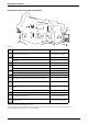
Interior components diagram and parts list 12.2.6 Group 6 4 8 5 6 7 9 10 11 3 2 1 14 15 16 12 13 6720902978.AA JF Fig. 70 Components Diagram Item Description Reference Item 1 Control unit 8 707 207 257 2 3 Fuse T2.5A Fuse T1.
Protecting the environment 13 Protecting the environment Packing The packing box may be fully recycled as confirmed by the recycling symbol . Components Many parts in the heater can be fully recycled in the end of the product life. Contact your city authorities for information about the disposal of recyclable products.
Limited Warranty 14 Limited Warranty General Service Labor Costs Aquastar water heaters are warranted by the Manufacturer (BOSCH) through BBT North America. BBT North America (BBTNA) will furnish a replacement heat exchanger and will furnish a replacement of any other part which fails in normal use and service within the applicable periods specified below, in accordance with the terms of this warranty. The BBTNA replacement will be warranted for the unexpired portion of the original warranty.
Installer Checklist to be completed by installer upon installation Serial Number ___ ___ ___ ___ ___ ___ ___ ___ (8 digit serial number is located on rating plate on right side panel) Gas Pressure Reading* Static__________ Operating__________ Building Water Pressure __________ Range if on Well system __________ Installing Company _____________________________________________ Installer name _____________________________________________ Address _____________________________________________ Phone