
Specifications


6 720 608 782
12
Installation instructions
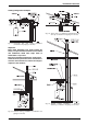
3.3.2 Condensate drain requirements
A condensate drain must be installed under the
following conditions:
• All vertical terminating vent installations
• Horizontal terminating vent installations where the
total equivalent exhaust vent length is greater than 10
feet. See table 17, page 33.
• Vent installations where any section of the exhaust
vent pipe passes through an unconditioned space.
Note: Do not install condensate drain in areas where it
may freeze.
1. Install condensate drain as close to heater as
possible.
2. Use 3/8" ID high temperature silicone tube to
connect to condensate drain port. Do not use copper
piping for any portion of the condensate drain.
3. Form a condensate trap by means of a 3" loop
partially filled with water.
4. To increase the tube length, connect to end of the
high temperature silicon tubing with vinyl tubing, PVC or
CPVC pipe. Do not reduce the internal diameter at any
point.
5. Dispose of condensate according to local codes.
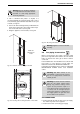
Fig. 15 Condensate drain installation
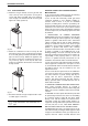
Room sealed installation (TWIN PIPE SYSTEM)
Installing this water heater as a room sealed (TWIN
PIPE SYSTEM) is the recommended method. Contact
your dealer for available vent termination kits and vent
materials for this water heater.
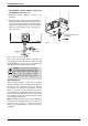
The exhaust and combustion air piping must vent
directly to the outside of the structure.
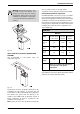
Fig. 16
Combustion air pipe: ≤ 26 ft (8 m) from collar
Exhaust vent pipe: ≤ 26 ft (8 m) from collar
Fig. 17
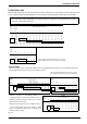
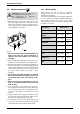
3" Venting Z-flex ProTech Heat Fab
90°
Condensate
Drain Tee
2SVEVWCF03 FST3 &
FSDF3
93PPLSTEE
Horizontal
Condensate
Drain
2SVEDWCF03 FSHDT3 9321
Condensate
Drain Tube
2SVEDTK24 N/A 7000TUBE
Table 7 Approved Condensate Drain Part Numbers
Warning: In areas where outside
temperatures commonly fall below
freezing, a twin pipe venting system is
required. Failure to do so may result in
cold outside air being drawn across the
heat exchanger coil causing it to freeze
and burst. This failure is not covered
under the manufacturer's warranty.