NEXT User manual Installation and Servicing instructions Important: This appliance is a domestic gas fired hot water heater and is intended for domestic use only INSTANTANEOUS MULTIPOINT GAS WATER HEATER TYPE C NEXT SFT 14 Country of destination GB, IE
User manual 1. General warnings ....................................................3 1.1. CE labelling .....................................................3 1.2. Safety regulations ...........................................3 2 User instructions. ....................................................4 2.1. Control panel...................................................4 2.1.2. Display .....................................................4 2.2. Initial set-up 2.3 Ignition procedure ........................
1. general information 1. GENERAL INFORMATION The Next SFT Water Heater is a room sealed, fanned flue, mulitpoint water heater. The appliance has been designed for domestic use only and to be connected to a mains cold water supply with a minimum pressure of 0.5 bar. A permanent electrical connection is required and should be provided by use of a fused spur. The electrical supply should be via a double pole isolating switch with 3mm contact separation in both poles.
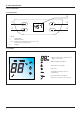
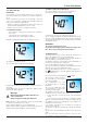
2. user instructions 2. Users Instructions 2.1. Control Panel 5 1 4 2 3 Legend: 1. Bath button 2. ON/OFF button 3 & 4. Temperature Buttons( Used to select hot water delivery temperature. 5. Display 2.1.2. Display - Water temperature indication (°C) - Signal error codes Water demand in progress Flame presence signal Fan active The display visualises the set temperature Reset procedure in progress Air pressure switch error (see 5.
2. user instructions 2.2. Initial Set-Up IMPORTANT: The installing technician should explain to the user how the water heater works, the safety devices it includes and how to use it. Before turning the water heater on, it should be connected to the electrical mains via a double pole isolating switch with 3mm contact separation in both poles. • Make sure that gas is supplied to the water heater (valve on gas pipe open) and purge any air as necessary • Make sure that the electrical supply is turned on. 2.4.
2. user instructions 2.6. Switching off procedure 2.7. Appliance shut-off conditions Press the ON/OFF button “2”, to switch off the appliance. The display indicates only two hyphens. To switch off the device completely, turn the external electric switch off and close the gas isolation valve. The appliance is protected from malfunctions by means of internal checks performed by the electronic P.C.B., which stops the appliance from operating if necessary.
2.
Installation and servicing instructions (Only for Gas Safe Registered Engineers) 3. Installation ...............................................................9 3.1. Description of the appliance ...........................9 3.2. Safety regulations .........................................10 3.3. Technical specifications ................................11 3.4. Operating principle .......................................12 3.5. Electrical circuit diagram .............................12 3.6.
3. installation 3.1. Description of the Appliance NEXT SFT water heaters are room sealed instantaneous gas fired water heaters, with electronic ignition and ionisation safety devices, they have a modulating burner and are connected to the mains water supply; they provide domestic hot water. Their self-contained combustion chambers with fans for the intake of external air and the extraction of combustion products, allow them to operate totally independently from the room in which they are installed.
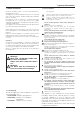
3. installation 3.2. Safety regulations Key to symbols: Failure to comply with this warning implies the risk of personal injury, in some circumstances even fatal Failure to comply with this warning implies the risk of damage, in some circumstances even serious, to property, plants or animals. Install the appliance on a solid wall which is not subject to vibration. Noisiness during operation.
3. installation 3.3. Technical Specification Model name : NEXT SFT 14 FF CE Certification (pin) 0051CM4057 Type C13 Gas category II2H3+ Maximum nominal heat input kW 28.0 Minimum nominal heat input kW 6.0 Maximum nominal heat output kW 25.0 Minimum nominal heat output kW 5.4 Domestic hot water temperature maximum °C 65 Domestic hot water temperature minimum °C 35 D.H.W. Nominal flow rate ΔT = 35ºC l/min 10.2 D.H.W.
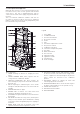
3. installation 3.4. Operating Principle Legend 1. Heat exchanger 2. Overheat thermostat 3. Detection Electrode 4. Burner 5. Fan 6. Outgoing water temperature sensor 7. Air pressure switch 8. Safety valve 9. Cold water inlet filter 10. Water flow switch 11. Inlet water temperature probe 12. Gas valve 13. Ignition electrode 1 2 13 3 4 12 5 6 11 7 10 8 9 C B D 3.5.
3. installation 3.6. Appliance Dimensions 120 Ø100 Ø60 51 145 22 22 38 563 599 613 B. C. D. G. 130 40 165 105 350 C D 60 B G 61 75 Hot water outlet 1/2” Gas inlet 3/4” Cold water inlet1/2” Drain valve Cold water inlet filter The following elements are supplied with the heater: 1x 15mm gas inlet isolation tap complete with washer 1x 15mmx1/2” swivel nut 90° brass connector for the hot water outlet complete with washer 1x 15mm cold water inlet isolating valve complete with washer 3.7.
3. installation 3.8. Reference Standards In the United Kingdom, the installation and initial start up of the water heater must be by a Gas Safe Registered installer in accordance with the installation standards currently in effect, as well as with any and all local health and safety standards. In the Republic of Ireland the installation and initial start up of the appliance must be carried out by a Competent Person in accordance with the current edition of I.S.
3. installation 3.8.2. Installing the Water Heater D B C C B F B. C. D. G.
3. installation IMPORTANT!! BE SURE TO REMOVE THE DISPLAY CABLE FROM THE PCB BEFORE COMPLETELY REMOVING THE CASING. 3.8.8. Wall Mounting Fix the water heater to the wall using suitably sized screws using both brackets at high and low level. 3.8.9.
3. installation 3.9. FITTING THE FLUE The appliance must not be installed with a flue supplied by another manufactuer. The appliance is supplied ready for connection to a concentirc air intake and exhaust outlet system. IMPORTANT!! The flue duct must not be in contact with inflammable materials, a seperation of at least 5mm must be between the flue duct and structures or walls made of flammable materials. When replacing an old appliance, the flue must be changed.
3. installation Once the appliance has been temporarily postitioned on the wall, insert the elbow into the socket and rotate to the required position. NOTE: IT IS POSSIBLE TO ROTATE THE ELBOW 360º ON ITS VERTICAL AXIS. Clamp Fig. 4 Either using the dimensions in Fig. 2 or physically marking the corresponding wall, remove the appliance from the wall and drill a Ø 105mm hole for the flue. Refit the appliance to the wall and proceed as follows: 1.
3. installation 3.9.4. Fitting the Coaxial Flue (Ø 60/100 Vertical) IMPORTANT!! The vertical starter with integral flue gas analysis point supplied with the flue kit must be used when terminating the flue vertically.
4. commissioning 4.4.1. Supply working pressure check 4. Commissioning Once the water heater installation has been completed, it is necessary to commision the appliance as follows: 4.1. Gas supply installation Inspect the entire installation including the meter, test for tightness and purge, as described in BS 6891. 4.2. Checking electricity supply Carry out preliminary checks for earth continuity, polarity, resistance to earth and short circuit.
4. commissioning 4.4.3. Checking the minimum pressure 1. 2. Close the gas isolation valve Loosen screw “a” and attach the manometer connection pipe into the pipe tap. 3. Open the gas isolation valve 4. Activate the appliance by opening a D.H.W. tap. 5. Press the SW2 button (on the P.C.B.), the appliance is forced to the minimum power. The display will show CL and a value from -9 to +9. Default value = 0 6.
5. appliance protection devices 5. Appliance shut-off conditions The appliance is protected from malfunctions by means of internal checks performed by the electronic P.C.B., which stops the appliance from operating if necessary. In the event of the appliance being shut off in this manner, a code appears on the control panel display which refers to the type of shut-off and the reason behind it. Switch off the appliance.
1. general information 6.1 Servicing instructions To ensure efficient safe operation, it is recommended that the water heater is serviced annually by a competent person. Before starting any servicing work, ensure both the gas and electrical supplies to the water heater are isolated and the water heater is cool. Before and after servicing, a combustion analysis should be made via the flue sampling point. After servicing, preliminary electrical system checks must be carried out to ensure electrical safety (i.e.
6. maintenance 9. A reading less than or equal to 0.008 following a service is a good indication that an appliance is operating safely and will continue to operate until the next planned service date. Even though the reading is above the 0.004 trigger value; 2. Remove the front cover. Pay attention to disconnect the display from the main PCB at the main PCB. C 10. For readings greater than 0.
6. maintenance 6.1.3 Removing the air pressure switch 1. Remove the 2 screws from the chassis A 6.1.4 Removing the fan 1. Release the 2 the two fan fixing screws, and remove the silicon pipe A 2. Remove the silicon pipe from the APS B 2. Disconnect the electrical connection from the main pcb B 2. Disconnect the electrical connection from the main pcb C 2. Remove the fan C 3.
6. maintenance 6.1.5 Removing the gas collector assembly 1. Remove the earth connection 4. Remove the gas collector D A 1. Release the 7 screws on the gas collector B 6.1.6 Removing the ignitor 1. Disconnect the electrical connections A 3. Release the screw also dismounts the igniter bracket C 2.
6. maintenance 3. Release the fixing screw Remove the spark generator C 6.1.7 Removing the ignition electrode 1. Release the 2 screws 6.1.8 Removing the detection electrode 1. Release the 2 screws A 2. Remove the electrode and disconnect the electrical connection B A 2.
6. maintenance 6.1.9 Removing the overheat thermostat 6.1.10 Removing the hot water temperature probe 1. Remove electrical connections 1. Remove the electrical connection A A 2. Release the 2 screws and remove the overheat thermostat B 2. Turn off the cold water isolation valve 3. Drain the appliance 4.
6. maintenance 6.1.11 Removing the inlet water temperature probe 1. Disconnet electrical connection A 6.1.12 Removing the water flow switch 1. Release the screw and disconnect the electrical connection A B 2. Turn off the cold water isolation valve and drain the appliance 3. Unscrew the 2 screws and remove the hot water temperature probe B 2. Turn off the cold water isolation valve and drain the appliance 3. Remove the clip from the pipe. B 4. Remove the temperature probe C 3.
6. maintenance 6.1.13 Removing the inlet water filter 1. Release the filter A 6.1.4 Removing the main P.C.B. 1. Release the 2 screws and dismount the PCB A 2. Remove the filter B 2.
6. maintenance 3 C Release the 4 screws fixing the cover of the main PCB and remove the other connection cables 6.1.15 Removing the display P.C.B. 1.
6. maintenance 6.1.16 Removing the gas valve 6.1.17 Removing the burner/heat exchanger 1. Remove the gas collector as detailed in 6.1.5 1. Remove electrical connections 2. Release the screw, release the silicone pipe from the fan assembly and remove the gas valve A A B 2. Remove the gas collector and the ignitor B 3.
6. maintenance 3. Disconnect the clips of the two pipe. Isolate the cold water inlet and drain the applianc C 4. Remove the fan as detailed in paragraph. 6.1.4 5. Release the 4 screws and dismount the heat exchanger, burner and combustion hood. F D 6. Remove the elctrodes and the overheat thermostat 7.
6. maintenance 8.
6. maintenance 6.4 Fault finding chart PRELIMARY CHECKS Make sure that: 1 - The mains water supply is turned on 2 - The gas is turned on 3 - The electrical supply is turned on PRESS THE ON/OFF BUTTON DRAW OFF WATER >2.
6. maintenance A IS THERE STILL A PROBLEM? NORMAL OPERATION FAULTS Drawing D.H.W.: insufficient hot water temperature Drawing D.H.W.
6.
6.
6.
TERMS AND CONDITIONS OF GUARANTEE Please read these terms and conditions which are in addition to any terms and conditions detailed in this book or any registration card supplied with your appliance. A charge will be made to the owner of the appliance if: · The reason for any service visit is as a direct result of a failure to install the appliance in accordance with the manufacturer’s instructions.