® INSTALLATION GUIDE RCC300-SM Subwoofer Module RCC300-FS Freestanding Subwoofer RCC300-SA Subwoofer Amplifier RCC300-CM Cabinet Mount I
Thank you for choosing Artison's RCC 300 Subwoofer System. We are pleased that you have selected our high-performance audio products. INTRODUCTION The following information will guide you through the installation and setup of your Artison RCC 300 Subwoofer Module, RCC 300 Freestanding Subwoofer, RCC 300 Subwoofer Amplifier and RCC 300 Cabinet Mount. Your RCC300-SM carton should contain the following: 1 1 1 1 . RCC . RCC . RCC .
RCC 300 SUBWOOFER MODULE (RCC300-SM) The RCC 300 Subwoofer Module can be installed into either an: • Artison Pre-Build Box (Volume ::= 0.6 ft3) SOLD SEPERATELY OR • Infinite Baffle (i.e. 2x4 stud wall, 16" On Center spacing at least 4 feet tall, Volume 1.4 fe or greater) IMPORTANT: In an installation of two RCC300-SM's that are being powered by one RCC300-SA, both Subwoofer Modules need to be in either Pre-Build Boxes or be in Infinite Baffles.
INSTALLATION INTO AN INFINITE BAFFLE 1. Use the provided Cut-out Template to mark the desired wall location. Be sure that no piping, wall studs, or electrical wires interfere with the placement of the RCC300-SM. 2. Once the hole is cut and the speaker wire is run, manage the speaker wire around the RCC300-SM. 3. Connect the bare speaker wire ends to the spring-loaded binding posts. 4. Install the RCC300-SM into the cut-out made in the wall. 5.
RCC 300 FREESTANDING SUBWOOFER (RCC300-FS) SUBWOOFER PLACEMENT AND ORIENTATION The RCC 300 Freestanding Subwoofer comes with four rubber feet to attach to the side of your choice. Carefully decide what placement and orientation are best for the subwoofer, the supplied rubber feet are not removable once applied. The classical rule for subwoofer placement is that the subwoofer should be placed near the same wall the front channels are located, at one-third of the total distance of the wall.
RCC 300 SUBWOOFER AMPLIFIER (RCC300-SA) The RCC 300 Subwoofer Amplifier can be installed into either cabinetry, on an equipment shelf, or it can be rack-mounted into a standard 19" Equipment Rack. In any installation be sure to provide adequate ventilation around the amplifier. The RCC300-SA has two simple and conveniently placed mode settings. The Music or Movie user controls are located on the front panel for selection based on the source material.
RCC300-SA FRONT PANEL CONTROLS '" RC(fLDJ / GAIN ·0· o • POWER DIM 0 0 10 IoIOVlE MUSIC 0 0 0 RTISON V '" GAIN - The position of this knob controls the overall gain (volume) of the subwoofer. Press this button in and it will spring out into a rotating knob, press it back in to hide it. The front panel gain control will become the master gain control until the remote is used. NOTE: The amplifier by default will resume to the last setting by either gain control device.
2. The Red Switch is the input voltage setting; select the appropriate 120V or 230V setting. 3. Connect the detachable IEC Power Cord underneath the Red Voltage Selection Switch. AUDIO OUTPUTS _ - - - - AUDIO OUTPUTS - - - - _ @€)@€) I I ~SUB1-= I I =-SUB2-@ 1. Connect the speaker wires to the Binding Posts. NOTE: Red is Positive and Black is Negative. 2. Use either Bare Speaker Wire or Banana Plugs to terminate the speaker wire. AUDIO INPUTS oro AUDIO OUTPUTS .
IR FEEDTHRU IR o 1. Connect a ~" Stereo MINIJACK to control the RCC600-SA via your integrated control system. 2. Both the IR Feedthru Jack and the Front Panel IR receiver are designed to allow the User functions to be programmed into an external remote. The Hexadecimal codes for the amplifier are located on the web at: http://www.artisonusa.com POWER MODES POWER MODES 0::: w eel Z ~el :::J ii: ~ +12V TRIGGER INPUT e < ~ rn 1. Select either: ON - Always On.
00 Baffle - The RCC 300 Subwoofer Module is installed in a wall that has an air volume of ~1.4 ft3. CLOSED BOX - The RCC 300 Subwoofer Module is installed in an Artison In-Wall Pre-Build Box or is the RCC 300 Freestanding Subwoofer. IMPORTANT: In an installation of two RCC300-SM's that are being powered by one RCC300-SA, both Subwoofer Modules need to be in either Pre-Build Boxes or be in Infinite Baffles.
to be raised to achieve the previous volume levels. If your normal listening position is located in a null, then the only way to truly even out the null is by either moving the subwoofer location to change the room modes that are stimulated OR install a distributed bass system. Distributed bass uses multiple subwoofers in different locations in order to stimulate more of the room modes.
RCC 300 CABINET MOUNT (RCC300-CM) The RCC 300 Cabinet Mount is an accessory for the RCC 300 Freestanding Subwoofer. The RCC300-CM allows the RCC300-FS to be hidden inside of any piece of furniture or built-in cabinetry. The subwoofer is designed to fit snuggly face-down inside the cabinet mount and direct the subwoofer's energy down through the bottom of the cabinet and either directly into the room or out through venting in the cabinet's baseboard. INSTALLATION 1.
LIMITED WARRANTY ALL INTERNET SALES ARE STRICTLY PROHIBITED This warranty remains in effect for five years from the date of purchase for speaker products and one year for electronic products. THIS WARRANTY PROTECTS THE ORIGINAL OWNER PROVIDING THAT THE PRODUCT HAS BEEN PURCHASED FROM AN AUTHORIZED ARTISON DEALER IN THE UNITED STATES. THE ORIGINAL BILL OF SALE MUST BE PRESENTED WHENEVER WARRANTY SERVICE IS REQUIRED.
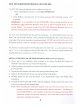
~- '. .- t 213mm-- Mounting Hole Cutout Dimensions ..--------. .a_slIII!. a.-..- ~ . Cut out opening N +:=-- Mark the cutout area by drawing through the slots surrounding the white area. ... "'4I - - - - - - - ...... ex> 3 3 w c.n 0') 3 3 ::J to I o - TEMPLATE CD () C 1""+ o WA~ING! Only cut out the ounting hole after you have verifi d there are no obstructions beHlind the dry wall. Before insta~ing check for obstructions b hind drywall by making a small hole. I _.o CD .., .., "'U .
~ 207mm - Mounting H Ie CU~9~t qimensions ~ I ~ Cut out opening Mark the cutout area by drawing through the slots surrounding the white area. ~---242mm N 00 00 3 3 s: o C :::J f""+ :::J TEMPLATE c.c I o- ~ (]I 3 3 m >< ., -. o ., f""+ "'U a CD () a. C (") f""+ o WAR\JING! Only cut out the mounting hole after you have verifibd there are no obstructions be~ind the dry wall. Before installing check for obstructions behind drywall by making a small hole. c..v c f""+ C o _. o_.
Name Address Company Telephone Number Date/Price Email Name of Dealer Address of Dealer Productlsl Model Numbers Please rate your overall experience with the dealer.
Place Stamp Here ARTISON Attention: Customer Service Department 774 Mays Blvd.