
Installation guide


HIGH PASS
HIGH PASS
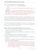
2. The Red Switch
is
the input voltage setting; select the appropriate 120V or 230V setting.
3.
Connect the detachable IEC Power Cord underneath the Red Voltage Selection Switch.
AUDIO OUTPUTS
_----
AUDIO OUTPUTS
----_
@€)@€)
I I I I
~SUB1-=
=-SUB2-@
1. Connect the speaker wires to the Binding Posts. NOTE: Red
is
Positive
and
Black
is
Negative.
2. Use either Bare Speaker Wire or Banana Plugs to terminate the speaker wire.
AUDIO INPUTS
AUDIO OUTPUTS
.-
AUDIO INPUTS
oro
BA~NCED
50?O
1. Connect to either the Balanced Female XLR or Unbalanced Female RCA Inputs.
NOTE:
Both
inputs
have been
calibrated
to
the
same
sensitivity
level.
AUDIO OUTPUTS
AUDIO OUTPUTS
.-
AUDIO INPUTS
orOh
50?O~
1. Connect to the Unbalanced Female RCA Outputs.
2. Set the High Pass Crossover to the desired frequency. The slope
is
set at 12 dB/octave.
9