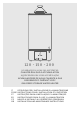
20 - 150 - 200 SCALDACQUA A GAS AD ACCUMULO 4:2G776ͻ62G 82L 244G?G>2F;A@ AQUECEDOR GÁS COM ACUMULAÇÃO 24G?G>25AD6E 56 28G2 42>;6@F6 2 82E LEA3@Ã=AHĘ A:õÃH2¢ HA5K 82Eͻ7;D65 EFAD286 I2F6D :62F6D ;F ;EFDGL;A@; B6D >ͭ;@EF2>>2L;A@6 6 >2 ?2@GF6@L;A@6 7D36 ;@EFDG4F;A@E BAGD >ͨ;@EF2>>2F;A@ 6F >ͨ6@FD6F;6@ BF ;@EFDGä6E B2D2 2 ;@EF2>2A 6 2 ?2@GF6@A 6E ;@EFDG44;A@6E B2D2 6> GEA K >2 ?2@GF6@4;Û@ 4L @HA5 = ;@EF2>24; 2 = Ă5Dĝ3® BDA A53AD@Ã=2 83 ;@EF2>>2F;A@ 2@5 ?2;@F6@2@46 ;@EFDG4F;A@E
ATTENZIONE! Il dispositivo contro le sovrapressioni, ove fornito in dotazione con il prodotto, non è un gruppo di sicurezza idraulico. GRUPPO SICUREZZA IDRAULICO Ai sensi della CIRCOLARE DEL MINISTERO DELLE ATTIVITA’ PRODUTTIVE DEL 26 MARZO 2003, N.
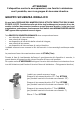
1.1 1.2 1.3 Solo per gli apparecchi predisposti • Uniquement pour les appareils prédisposés • Solo para los modelos predispuestos Only for equipped appliances • Nur für die dafür vorgesehenen Geräte bestimmt! • Enkel voor voorbestemde toestellen Sómente para aparelhos pre-vistos • Tylko w wybranych urządzeniach • Pouze pro spotrebice k tomu urcené Iba pre spotrebice k tomu urcené • Csak előre beállított készülékekre • Doar pentru echipamente avand anumite componente ТОЛЬКО ДЛЯ ОПРЕДЕЛЕННЫХ МОДЕЛЕЙ 2.
IT PER LA VOSTRA SICUREZZA In caso di odore di gas: 1. Chiudere immediatamente il rubinetto del gas. 2. Aprire le finestre 3. Non azionare interruttori elettrici o qualsiasi altra apparecchiatura elettrica. 4. Spegnere la fiamma pilota. 5. Richiedere immediatamente l’intervento di un tecnico dell’Azienda del gas ATTENZIONE Non immagazzinare o impiegare materiali o liquidi infiammabili nelle vicinanze dell’apparecchio • L’installazione dell’apparecchio deve essere eseguita da un installatore specializzato.
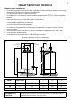
IT CARATTERISTICHE TECNICHE L’apparecchio è costituito da: • un serbatoio protetto internamente da uno strato di smalto vetrificato, dotato di un anodo di protezione contro la corrosione di lunga durata; • un rivestimento esterno in lamiera verniciata; • un isolamento in schiuma poliuretanica ad alta densità (senza CFC) che riduce le perdite termiche; • una cappa fumi contro il riflusso dei gas di combustione; • una valvola gas completa di: un termostato regolabile a più posizioni, un sistema di sicurezza
IT NORMATIVE APPLICABILI PER L’INSTALLAZIONE Eseguire l’installazione in conformità alle norme: - UNI-CIG 7129 - 7131 1. POSIZIONAMENTO qua nell’angolo fra due pareti, mantenere, tra la parete e l’apparecchio, una distanza sufficiente per l’installazione e lo smontaggio dei componenti. 1.1. Posizionare l’apparecchio accanto alla parete prescelta in modo che i due tubi di entrata e uscita siano paralleli ad essa. 1.2 Se si dovesse installare lo scaldac- 2.
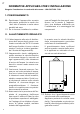
sotto lo zero. All’atto della installazione prevedere tale eventualità e collegare un rubinetto di scarico al raccordo R (fig. 4). 3 IT PER SVUOTARE LO SCALDACQUA È NECESSARIO: 2.6.
IT 4. ALLACCIAMENTO AL CAMINO 4.1. È indispensabile che i gas combusti siano scaricati all’esterno mediante un tubo di diametro adeguato al diametro L int (tabella dimensioni di ingombro fig. 1) inserito sulla cappa dell’apparecchio 4.2. È importante che il camino abbia un buon tiraggio. 4.3. Evitare nel condotto di evacuazione lunghi tratti orizzontali, contropendenze e strozzature. Sono cause di cattiva combustione. 4.4.
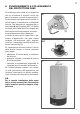
IT 6. FUNZIONAMENTO E COLLEGAMENTO DEL PROTETTORE FUMI Gli scaldacqua sono dotati di un dispositivo che ha la funzione di bloccare l’arrivo del gas al bruciatore e quindi di interrompere il funzionamento dell’apparecchio quando la canna fumaria è parzialmente o totalmente ostruita. Tale dispositivo è composto da un termostato A (fig. 6) tarato a 85°C ± 3 fissato sul bordo della cappa fumi C e collegato alla termocoppia ed al termostato di sicurezza di sovratemperatura della valvola gas.
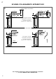
IT SCHEMA COLLEGAMENTO APPARECCHIO 8 SCARICO DIRETTO ALL'ESTERNO 1m max 1m max 2d min. Pente mini 3% 2d min. 3d min.
ISTRUZIONI TECNICHE PER L’INSTALLAZIONE NORMATIVE DI RIFERIMENTO L’installazione e la prima accensione dell’apparecchio deve essere effettuata da personale qualificato in conformità alle seguenti normative di riferimento: - Legge 6 Dicembre 1971 N. 1083; - “UNI-CIG”7129 /7131; Nella installazione devono essere rispettate le norme dei Vigili del Fuoco, della locale Azienda del Gas e dell’Ufficio Igiene del Comune.
IT 10 La sezione dell’apertura deve essere di misura adeguata. L’apertura è sufficientemente ampia da consentire una aerazione adeguata all’apparecchio. SÌ d 11 NO La sezione dell’apertura è insufficiente L’apertura non è sufficiente ad alimentare l’apparecchio e il caminetto il quale deve avere una apertura propria dl alimentazione d’aria (rivolgersi al costruttore del camino).
AERAZIONE INDIRETTA Nel caso non sia possibile effettuare l’aerazione direttamente nel locale, si può ricorrere alla ventilazione indiretta, con prelievo d’aria da un locale attiguo attraverso un’adeguata apertura praticata nella parte bassa della porta.
IT 7. ISTRUZIONE PER L’ACCENSIONE E LO SPEGNIMENTO CON VALVOLA EUROSIT 7.1. ACCENSIONE Portare la manopola (1) dalla posizione (= spento) alla posizione (= pilota). Premere a fondo per circa 20 secondi la manopola 1 ed agire sul pulsante piezolettrico 2 più volte per accendere il pilota (controllare dall’apertura 3). Se lasciando la manopola 1 il pilota si spegne, ripetere l’operazione e tenere premuto più a lungo finché la fiammella non rimane accesa.
IT MANUTENZIONE Si raccomanda di effettuare sull’apparecchio, almeno una volta l’anno, i seguenti controlli: 1 Controllo della tenuta parte acqua. 2 Controllo della tenuta della parte gas con eventuale sostituzione delle guarnizioni. 3 Controllo visivo dello stato complessivo dell’apparecchio e della combustione. 4 Controllo visivo della camera di combustione ed eventuale pulizia del bruciatore. 5 A seguito del controllo punto 3 e 4, eventuale smontaggio e pulizia dell’ugello.
IT RISERVATO ALL’INSTALLATORE Istruzioni per l’adattamento al funzionamento con gas diverso sa quello di taratura ATTENZIONE! Gli apparecchi di categoria II2H3+ sono normalmente tarati per funzionamento a gas metano G20 e sono adattabili al funzionamento con gas liquido G30-G31 SMONTAGGIO GRUPPO GAS E CAMBIO UGELLI Per adattare lo scaldacqua ad un gas diverso da quello di taratura si deve sostituire l’ugello del bruciatore principale e del pilota.
IT CAMBIO DEGLI UGELLI a) Svitare l’ugello principale 10 (fig. 16) e sostituirlo. b) Sostituire l’ugello 3 (fig. 19) del pilota come segue: • svitare completamente la vite di fissaggio 2 • allentare completamente il raccordo 4 • sostituire l’ugello 3 • rimontare eseguendo le operazioni all’inverso 18 RIMONTAGGIO DEL GRUPPO GAS • Rimontare il gruppo eseguendo le operazioni indicate nel paragrafo “SMONTAGGIO DEL GRUPPO GAS” in senso inverso.
IT VERIFICA DELLE TARATURE SULLA VALVOLA GAS NOTA Per gli appparecchi di categoria II2H3+, predisposti per il funzionamento a gas metano G20, la taratura è già stata effettuata in fabbrica; nessuna regolazione è pertanto richiesta con questo gas. Per l’adattamento al funzionamento con gas liquido G30-G31, sarà sufficente sostituire gli ugelli del bruciatore principale e del pilota. PRESSIONE DI ALIMENTAZIONE (gas naturale e gas liquido).
di sicurezza acqua (limite di temperatura e pressione, valvola idraulica) • verificare il funzionamento dei sistemi di sicurezza gas (valvola gas, mancanza gas o fiamma ecc...) • verificare lo stato del deflettore fumi • verificare le caratteristiche di ventilazione del locale e di evacuazione dei prodotti della combustione. • pulire il condotto fumi. Prima di fare questo è necessario togliere il gruppo gas e sfilare il deflettore fumi.
IT DATI TECNICI Identificativo del modello del fornitore Modello Certificato CE Capacità nominale Capacità reale Pressione nominale Portata termica nominale Potenza utile Tempo di riscaldamento ACS t 45°C Dispersione di calore a 60° C Portata acqua calda Erogazione a 30K Erogazione a 45K Erp Profilo di carico dichiarato Efficienza energetica di riscaldamento dell’acqua ηwh Classe energetica Consumo quotidiano di energia elettrica Qelec Consumo quotidiano di combustibile Qfuel Livello di potenza sonora LWA Em
IT RACCOMANDAZIONI PER PREVENIRE LA PROLIFERAZIONE DELLA LEGIONELLA (in base alla norma europea CEN/TR 16355) INFORMATIVA La Legionella è un batterio di piccole dimensioni, a forma di bastoncino ed è un componente naturale di tutte le acque dolci. La Malattia del Legionario è una seria infezione polmonare causata dall’inalazione del batterio Legionella pneumophilia o di altre specie di Legionella.
FR/BE POUR VOTRE SÉCURITÉ En cas d’odeur de gaz: 1. Fermer immédiatement le robinet d’arrivée du gaz. 2. Ouvrir les fenêtres. 3. Ne pas actionner d’interrupteurs électriques ou autres appareils électriques. 4. Éteindre la flamme pilote. 5. Demander immédiatement l’intervention d’un technicien de la société du gaz. ATTENTION Ne pas emmagasiner ou utiliser des matériaux ou des liquides inflammables à proximité de l’appareil • L’installation de l’appareil doit être effectuée par un installateur spécialisé.
FR/BE CARACTÉRISTIQUES TECHNIQUES L’appareil est constitué de: • une cuve protégée à l’interne par une couche d’émail vitrifié et dotée d’une anode de protection longue durée contre la corrosion; • un revêtement externe en tôle péinte; • une isolation en mousse de polyuréthanne à haute densité (sans CFC) qui réduit les pertes thermiques; • un coupe tirage; • une valve gaz complète de: thermostat réglable sur plusieurs positions, un système de sécurité à thermocouple, un limiteur de température qui interro
FR/BE 1. POSITIONNEMENT 1.1. Positionner l’appareil à côté de la paroi désirée de manière à ce que les deux tuyaux d’entrée et de sortie lui soient parallèles. 1.2 Si l’installation du chauffe-eau est prévue sur l’angle de deux parois, il faut prévoir entre la paroi et l’appareil une distance suffisante à l’installation et au démontage des composants. 1.3 Le dispositif de vidange est situé dans la partie inférieure droite prévue pour l’installation d’un robinet de vidange. 1.
FR/BE au-dessous de zéro. Lors de l’installation, prévoir cette éventualité et raccorder un robinet de vidange au raccord R (fig. 4). 3 POUR VIDER LE CHAUFFE-EAU IL FAUT: 2.6.
FR/BE 4. RACCORDEMENT À LA CHEMINÉE 4.1. Les gaz brûlés doivent obligatoirement être évacués à l’exterieur par le biais d’un tuyau de diamètre adéquat au diamètre L int (tableau dimensions d’encombrement fig. 1), introduit sur le coupe tirage de l’appareil. 4.2 La cheminée doit avoir un bon tirage. 4.3 Eviter, dans le conduit d’évacuation, de longs segments horizontaux, des contrepentes et des étranglements car ceci peut provoquer une mauvaise combustion. 4.
FR/BE 6. FONCTIONNEMENT ET RACCORDEMENT DE LA PROTECTION FUMÉES Les chauffe-eau sont dotés d’un dispositif qui a la fonction de bloquer l’arrivée du gaz au brûleur et donc d’interrompre le fonctionnement de l’appareil quand le conduit de fumée est partiellement ou totalement obstrué. Ce dispositif est composé d’un thermostat A (fig. 6) taré à 85°C ± 3 fixé sur le bord du coupe tirage C, raccordé en série sur le circuit du thermocouple.
FR/BE SCHÉMA DE RACCORDEMENT DE L’APPAREIL 8 SORTIE DIRECTE À L’EXTERIEUR SCARICO DIRETTO ALL'ESTERNO 1m max 1m max 2d min. Pente mini Pente3% mini 3% 2d min. 3d min.
FR/BE 7. INSTRUCTIONS POUR L’ALLUMAGE ET L’EXTINCTION 7.1. ALLUMAGE Porter le sélecteur 1 de la position (éteint) à la position (veilleuse). Pousser à fond le sélecteur 1, après 4 à 5 secondes environ, actionnez plusieurs fois l’allumeur piézo-électrique 2 pour allumer la veilleuse (contrôler à travers l’ouverture 3).
FR/BE RÉSERVÉ À L’INSTALLATEUR INSTRUCTIONS POUR LE CHANGEMENT DE GAZ PRESCRIPTIONS Les appareils de catégorie II2E+3+ sont normalement réglés pour fonctionner au gaz naturel G20-G25 et sont adaptables pour fonctionner au gaz butane/propane G30G31. DÉMONTAGE DU GROUPE GAZ ET REMPLACEMENT DES INJECTEURS Pour adapter le chauffe-eau à un gaz différent de celui d’origine, il faut remplacer le gicleur du brûleur principal et de la veilleuse.
CHANGEMENT DES INJECTEURS a) Dévisser le gicleur principal 10 (fig. 10) et le remplacer. b) Remplacer l’injecteur 3 (fig. 13) de la veilleuse comme suit: • dévisser complètement la vis de fixation 2 • desserrer complètement le raccord 4 • remplacer le gicleur 3 • remonter l’ensemble en procédant dans l’ordre inverse du démontage. REMONTAGE DU GROUPE GAZ • Remonter le groupe en procédant dans l’ordre inverse aux opérations indiquées dans le paragraphe “DÉMONTAGE DU GROUPE GAZ”.
FR/BE VÉRIFICATION DU REGLAGE DE LA VALVE GAZ NOTE Relativement aux appareils de catégorie II2E+3+ regles pour fonctionner au gaz naturel G20G25, le reglage a été effectué en usine; aucun autre réglage n’est donc nécessaire avec ce type de gaz. En ce qui concerne l’adaptation pour fonctionner au gaz butane/propane G30G31, il suffit de remplacer les injecteurs des brûleur principal et de la veilleuse.
• vérifier l’état du déflecteur fumées • vérifier les caractéristiques de ventilation des lieux et d’évacuation des produits de la combustion • nettoyer le conduit fuméegas o fiamma ecc...) • Avant d’effectuer cette opération, il faut enlever le groupe gaz et sortir le déflecteur fumées. Après cette opération, vérifier l’étanchéité du groupe gaz et son reglage. N.B.: La cuve interne du chauffe-eau ne doit pas, pendant cette opération, subir des heurts qui peuvent endommager son revêtement interne. 4.
FR/BE DONNÉES TECHNIQUES Identification du modèle du fournisseur Modèle Certificat CE Capacité nominale I Capacité réelle I Pression nominale bars Débit calorifique nominal kW Puissance utile kW Temps de chauffage ECS t 45°C min.
FR/BE RECOMMANDATIONS POUR EMPÊCHER LA PROLIFÉRATION DES LÉGIONELLES (sur la base de la norme européenne CEN/TR 16335) NOTICE D’INFORMATION Les légionelles sont des bactéries de petite dimension, en forme de bâtonnet, qui se trouvent naturellement dans toutes les eaux douces. La maladie du légionnaire est une infection pulmonaire grave, provoquée par l’inhalation de la bactérie Legionella pneumophilia ou d’autres espèces de Legionella.
ES PARA SU SEGURIDAD EN CASO DE OLOR A GAS: 1. Cierre inmediatamente la llave del gas. 2. Abra las ventanas 3. No accione interruptores eléctricos o cualquier otro aparato eléctrico. 4. Apague la llama piloto. 5. Solicite inmediatamente la intervención de un técnico de la Empresa de gas. AATENCIÓN! No almacene ni emplee materiales o líquidos inflamables en las cercanías del aparato. • La instalación del aparato debe efectuarse por un instalador especializado.
ES CARACTERÍSTICAS TÉCNICAS EL APARATO ESTÁ CONSTITUIDO POR: • un depósito protegido internamente por una capa de esmalte vitrificado, provisto de un ánodo de protección contra la corrosión, de duración prolongada; • un revestimiento externo en chapa pintada; • un aislamiento en espuma poliuretánica a alta densidad (sin CFC) que reduce las pérdidas térmicas; • una campana para humos contra el reflujo de los gases de combustión; • una válvula de gas provista de: un termostato regulable a distintas posicione
ES 1. EMPLAZAMIENTO 1.1. Emplace el aparato cerca de la pared elegida de manera que los dos tubos de entrada y salida resulten paralelos a la misma. 1.2 En caso de que el calentador de agua deba instalarse en una esquina entre dos paredes, mantenga, entre la pared y el aparato, una distancia suficiente para la instalación y el desmontaje de los compo- nentes. 1.3 El dispositivo de vaciado está situado en la parte inferior derecha, donde es necesario colocar un grifo para el vaciado. 1.
biente bajo cero. Al momento de la instalación, tenga en cuenta dicha eventualidad y conecte un grifo de vaciado a la unión R (fig.4). 3 ES PARA EL VACIADO DEL CALENTADOR DE AGUA ES NECESARIO: 2.6. VACIADO Proceda al vaciado del aparato cuando el mismo tuviese que permanecer inactivo en locales no calefaccionados, a temperaturas am- • apagar el quemador y cerrar la alimentación del gas • cerrar el grifo de paso situado arriba del aparato.
ES 4. CONEXIÓN A LA CHIMENEA 4.1. Es indispensable que los gases de combustión se evacúen al exterior mediante un tubo de diámetro adecuado al diámetro L int (tabla dimensiones fig. 1) introducido en la campana del aparato. 4.2 Es importante que la chimenea posea un buen tiraje. 4.3 Evite, en el conducto de evacuación largos tramos horizontales, contrapendientes y estrangulamientos puesto que pueden causar mala combustión. 4.
ES 6. FUNCIONAMIENTO Y CONEXIÓN DEL PROTECTOR DE HUMOS Los calentadores de agua están dotados de un dispositivo que tiene la función de bloquear la llegada del gas al quemador y por consiguiente interrumpir el funcionamiento del aparato cuando el conducto de humos resulta parcial o totalmente obstruido. Dicho dispositivo está compuesto de un termostato A (fig.
ES 7. INSTRUCCIONES PARA EL ENCENDIDO Y EL APAGADO CON VÁLVULA EUROSIT 7.1. ENCENDIDO Girar la manivela 1 desde la posición (apagado) hasta la posición (piloto). Apretar hasta el fondo la manivela 1 durante unos 20 segundos y pulsar repetidamente el botón piezoeléctrico 2 hasta encender el piloto (controlar a través de la apertura 3). Si al soltar la manivela 1 el piloto se apaga, repetir la operación y continuar apretando hasta que la llama quede encendida.
ES RESERVADO AL INSTALADOR INSTRUCCIONES PARA LA ADAPTACIÓN AL FUNCIONAMIENTO CON UN GAS DIFERENTE AL DE REGULACIÓN PRESCRIPCIONES Los aparatos de categoría II2H3+ se regulan normalmente para el funcionamiento con gas metano G20 y se adaptan al funcionamiento con gas líquido G30-G31. DESMONTAJE DEL GRUPO GAS Y CAMBIO DE LOS INYECTORES Para adaptar el calentador de agua a un gas diferente al de regulación se debe sustituir el inyector del quemador principal y del piloto.
ES SOSTITUCION DE LOS INYECTORES a) Destornillar el inyector principal 10 (fig.9) y sustituirlo con uno nuevo. b) Sustituir el inyector 3 (fig.12) del piloto de la siguiente manera: • afloje completamente el tornillo de fijación 2 • afloje completamente el racord 4 • sustituir el inyector 3 • vuelva a montar efectuando las operaciones en sentido inverso. 11 REMONTAJE DEL GRUPO GAS • Vuelva a montar el grupo efectuando las operaciones indicadas en el párrafo “DESMONTAJE DEL GRUPO GAS” en sentido inverso.
ES VERIFICACIÓN DE LAS REGULACIONES EN LA VÁLVULA DEL GAS NOTA En los aparatos de categoría II2H3+, predispuestos para el funcionamiento con gas metano G20, la regulación ha sido ya efectuada en fábrica, por lo tanto con este gas no se requiere ningún tipo de regulación. Para la adaptación al funcionamiento con gas líquido G30-G31, será suficiente sustituir los inyectores del quemador principal y del piloto. PRESIÓN DE ALIMENTACIÓN (gas natural y gas líquido).
ES • verificar el funcionamiento de los sistemas de seguridad del agua (límite de temperatura y presión, válvula hidráulica) • verificar el fucionamiento de los sistemas de seguridad del gas (válvula del gas, falta de gas o llama etc...) • verificar el estado del deflector de humos • verificar las características de ventilación del local y de evacuación de los productos de la combustión. • limpiar el conducto de humos. Antes de efectuar esto es necesario quitar el grupo gas y extraer el deflector de humos.
ES DATOS TÉCNICOS Identificación del modelo del proveedor Modelo Certificado CE Capacidad nominal Capacidad real Presión nominal Capacidad térmica nominal Potencia útil Tiempo de calentamiento del ACS t 45 °C Dispersión de calor a 60 °C Caudal de agua caliente Suministro a 30 K Suministro a 45 K Erp Perfil de carga declarado Eficiencia energética de calentamiento del agua ηwh Clase energética Consumo diario de energía eléctrica Qelec Consumo diario de combustible Qfuel Nivel de potencia sonora LWA Emisione
ES RECOMENDACIONES PARA PREVENIR LA PROLIFERACIÓN DE LA LEGIONELLA (en base a la norma europea CEN/TR 16355) NOTA INFORMATIVA La Legionella es una pequeña bacteria, que tiene forma de bastoncillo y es un componente natural de todas las aguas dulces. La Legionelosis es una seria infección de los pulmones causada por la inhalación de la bacteria Legionella pneumophilia o de otras especies de Legionella.
PELA VOSSA SEGURANÇA PT EM CASO DE CHEIRO DE GÁS: 1. Fechar imediatamente a torneira do gás 2. Abrir as janelas 3. Não acionar interruptores eléctricos ou quaisquer aparelhos eléctricos 4. Desligar o chama piloto. 5.
PT CARACTERÍSTICAS TÉCNICAS O aparelho é formado de: • um tanque protegido internamente por uma camada de esmalte vitrificado, equipado de um ânodo de proteção contra a corrosão contra o tempo.
PT 1. POSICIONAMENTO 1.1. Posicionar o aparelho ao lado da parede pre-escolhida de maneira que os dois tubos de entrada e saída sejam paralelos àquela. 1.2 Se o termoacumulador é instalado no canto entre duas paredes, manter, entre a parede e o aparelho, uma distância suficiente para a instalação e desmontagem das peças. 1.3 O dispositivo de evacuação encontra-se na parte inferior direita, onde deve ser instalada uma torneira de descarga. 1.
PT esta eventualidade colocando uma torneira de descarga na junção R (fig. 4). PARA ESVAZIAR O TERMOACUMULADOR É NECESSÁRIO: • desligar o queimador e fechar a alimentação do gás • fechar a torneira de interceptação na parte superior do aparelho • abrir as torneiras de utilização na parte inferior do aparelho • abrir a torneira de descarga ligada a junção R. 3 2.6 DESCARGA Se o aparelho estiver inativo, em locais não aquecidos, com temperaturas abaixo de zero, esvaziar o aparelho.
PT 4. LIGAÇÃO A CHAMINÉ 4.1. E’ indispensável que os gases de combustão sejam descarregados ao exterior mediante um tubo de diâmetro adequado ao diâmetro L int (tabela dimensões externas fig. 1) ilustrado sobre a capa do aparelho 4.2 E’ importante que a chaminé tenha um bom sistema de tiragem. 4.3 Evitar, que o tubo de evacuação seja longo e horizontal demais, que não seja torto pois poderia causar má combustão. 4.
PT 6. FUNCIONAMENTO E LIGAÇÃO DO PROTETOR DOS FUMOS O termoacumulador a gás são dotados de um dispositivo que tem a função de bloquear a chegada do gás ao queimador e assim de interromper o funcionamento do aparelho quando a chaminé está em parte ou totalmente obstruída. Este dispositivo é composto de um termostato A (fig. 6) tarado a 85°C ± 3 fixado sobre a borda da capa dos fumos C e ligado a um termopar e ao termostato de segurança de sobreaquecimento.
7. INSTRUÇÕES PARA A ACENSÃO E O DESLIGAMENTO COM A VÁLVULA EUROSIT 7.1. ACENSÃO Por o botão 1 da posição (apagado) na posição (piloto). Apertar a fundo por cerca de 20 segundos o botão 1 e agir sobre o botão piezoeléctrico 2 várias vezes para acender o piloto (controlar pela abertura 3). Se soltando o botão 1 o piloto se apaga, repetir a operação e apertar o botão por mais tempo até que a chama permaneça acesa.
PT RESERVADO AL INSTALADOR INSTRUÇÕES PARA SUBSTITUÇÃO DOS INJECTORES PARA FUNCIONAMENTO COM GÁS DIFERENTE PRESCRIÇÕES Os aparelhos de categoria II2H3+ são normalmente tarados para o funcionamento a gás metano G20 e são adaptáveis ao funcionamento com gás liquido G30-G31.
PT SUBSTITUIR AS BÔCAS a) Desparafusar a boca principal 10 (fig. 9) e substitui-la b) Substituir a boca 3 (fig. 12) do piloto como a seguir-se indica: • desparafusar completamente o parafuso de fixação 2 • largar completamente a junção 4 • substituir a boca 3 • tornar a montar seguindo as operações na maneira inversa. 11 REMONTAGEM DO GRUPO GÁS • Remontar o grupo efetuando as operações indicadas no parágrafo “DESMONTAGEM DO GRUPO GÁS” no sentido inverso.
PT VERIFICAÇÃO DAS AFINAÇÕES DA VÁLVULA DE GÁS NOTA Para os aparelhos de categoria II2E+3+, predispostos para o funcionamento a gás metano G20, a afinação está feita na fabrica; nenhuma regulação extra é necessário, para a adaptação ao funcionamento com gás liquido G30-G31, será suficiente substituir os injectores do queimador principal e do piloto. PRESSÃO DE ALIMENTAÇÃO (gás natural e gás liquido) GPL.
• verificar o estado do defletor fumos • verificar as características de ventilação do local e de evacuação dos produtos da combustão. • limpar o tubo de exaustão dos fumos. Antes de acabar é necessário tirar o grupo gás e tirar o defletor dos fumos. Após esta operação, verificar o circuito gás e a afinação de todo o grupo. NB: O corpo interno do aquecedor não deve, no curso da operação, sofrer golpes que possam danificar a proteção interna 4.
PT DADOS TÉCNICOS Identificação do modelo do fornecedor Modelo Certificado CE Capacidade nominal Capacidade real Pressão nominal Débito calorífico nominal Potência útil Tempo de aquecimento ACS t 45 °C Dispersão de calor a 60 °C Débito de água quente Fornecimento a 30K Fornecimento a 45K Erp Perfil de carga declarado Eficiência energética de aquecimento da água ηwh Classe energética Consumo quotidiano de energia elétrica Qelec Consumo quotidiano de combustível Qfuel Nível de potência sonora LWA Emissões de
PT RECOMENDAÇÕES PARA PREVENIR A PROLIFERAÇÃO DE LEGIONELA (de acordocom a norma europeia CEN/TR 16355) NOTA INFORMATIVA A Legionela é uma bactéria de pequenas dimensões, em forma de bastão e é um componente natural de todas as águas doces. A Doença do Legionário é uma grave infeção pulmonar causada pela inalação da bactéria Legionella pneumophilia ou de outras espécies de Legionela.
CZ PRO VAŠI BEZPEČNOST Pokud ucítíte zápach plynu: 1. Neprodleně uzavřete přívod plynu. 2. Otevřete okna. 3. Nespouštějte žádné elektrické přístroje ani neotáčejte elektrickými vypínači. 4. Vypnēte zapalovací plamínek. 5. Zavolejte servisní organizaci. POZOR! V blízkosti zařízení nepoužívejte a neukládejte hořlavé materiály a kapaliny. • Instalaci zařízení musí provést náležitě kvalifikovaná osoba. • Pro dosažení správného a bezpečného chodu zařízení je nutno respektovat následující instrukce.
CZ TECHNICKÀ CHARAKTERISTIKA Zařízení se skládá z: • ocelového zásobníku na vnitřní straně chráněného vrstvou smaltu a vybaveného anodou, která zjišťuje dlouhodobou ochranu proti korozi; • vnějšího pláště z ocelového, bíle lakovaného plechu; • tepelné izolační vrstvy z polyuretanové pěny; • kouřovodu zajišťujícího odtah spalin; • plynového ventilu vybaveného: provozním termostatem, pojistným zařízením na bázi termočlánku, havarijním termostatem, který zajistí přerušení přívodu plynu v případě přehřátí; • h
CZ 1. UMÍSTĚNÍ 1.1. Bojler je určen k postavení na pevnou podložku 2. Minimální vzdálenosti od stěny viz. obr. A Instalace musí odpovídat příslušným ČSN a musí být provedena kvalifikovaným odborníkem. Uvedení do chodu může provést jen technik oprávněny výrobcem. 2. ZAPOJENÍ ROZVODU VODY 64 B C 20 cm. 2.1. Bojler se připojuje na rozvod vody 3/4”. Vpravo je přívod studené vody (modrá krytka), vlevo výstup teplé vody (červená krytka). 2.2.
CZ 3. PŘIPOJENÍ RECIRKULACE 3.1 ZPĚTNÝ OKRUH Na šroubení R bojleru lze při delších rozvodech TUV zapojit zpětný okruh teplé vody viz. obr. D. D jednosm rny ventil valvola unidirezionale T U E rozvod TUV utilizzazione valvola di sicurezza přívod alimentazione S R ricircolazione T vypustny scarico kohout ODVOD SPALIN Bojler je spotřebič typu B. Musí být připojen na komín s dostatečným odvodem spalin. Provedení odvodu spalin musí splňovat podmínky ČSN.
CZ 4. NAPOJENÍ NA KOMÍN 4.1. Je nezbytné aby byly spaliny odváděny prostřednictvím trubky s vnitřním rozměrem odpovídajícím údaji „L“ v tabulce „Rozměry“ (viz obr. 1) zasazené do přerušovače tahu (viz obr. 5). 4.2 Je důležité, aby komín měl dostatečný tah. 4.3 Pro zajištění správného spalování by na kouřovodu neměly být dlouhé vodorovné úseky, úseky se záporným sklonem, četná kolena či záhyby. 4.
CZ 6. PROVOZ A ZAPOJENÍ POJISTKY PROTI ZPĚTNÉMU TOKU SPALIN Ohřívače vody jsou vybaveny zařizením, jehož funkce spočíva v přerušení přístupu plynu do hořáku - a tedy v přerušení chodu ohřívače - v případe částečného nebo úplného ucpání odtahového potrubí a komína. Toto zařízení se skládá z termostatu A (obr. L) nastaveného na 85° C ÷ 3 umístěného na okraji přerušovače tahu spalin C a napojeného na termočlánek a havarijní termostat přehřátí plynového ventilu.
CZ SCHEMA ZAPOJENÍ PŘÍMÉ ODKOUŘENÍ PŘES ZEĎ 8 SCARICO DIRETTO ALL'ESTERNO 1m max 1m max 2d min. Pente mini Minimální 3% skion 3% 2d min. 3d min.
TECHNICKŰ INSTRUKCE PRO INSTALCI ODPOVÍDAJÍCÍ NORMY Instalace a uvedení do provozu musí být provedeno v hradně náležitě kvalifikovanou osobou a v souladu s následujícími normami: ČSN 06 0310 Ústřední vytápění, projektování, montáž ČSN 06 0320 Ohřívač užitkové vody – navrhování a projektování ČSN 06 0830 Zabezpečovací zařízení pro ústřední vytápění a ohřev užitkové vody ČSN 06 1008 Požární bezpečnost lokálních spotřebičů a zdrojů tepla /do 50 kW) ČSN 06 1610 Části kouřovodů domácích spotřebičů ČSN 07 0240 T
CZ 10 Plocha větracího otvoru musí být dostatečná Větrací otvor je dostatečně velký a zajišťuje přísun vzduchu pro spalování. ANO d 11 Plocha větracího otvoru neposkytuje dostatečný přísun vzduchu pro plynový spotřebič a krb (obraťte se na dodavatele krbu). d 12 NE Plocha větracího otvoru neposkytuje dostatečný přísun vzduchu pro plynový spotřebič a ventilátor (velikost větracího otvoru upravte dle níže uvedené tabulky).
NEPŘÍMÉ VĚTRÁNÍ V případě, že není možné zajistit přímou ventilaci v místnosti osazení lze zajistit ventilaci zmístnosti vedlejší, a to prostřednictvím mřížky umístěné v dolní části dveří. Toto řešení je ovšem možné pouze: • je-li ve vedlejší místnosti přímý větrací otvor odpovídajícího rozměru; • vedlejší místnost neslouží jako ložnice; • vedlejší místnost není společným domovním prostorem ani prostorem se zvýšeným nebezpečím požáru (například garáž).
CZ 7. NÁVOD NA SPUŠTĚNÍ A VYPNUTÍ S VENTILEM EUROSIT 7.1. SPUŠTĚNÍ Ovládací prvek 1 přepněte z polohy (vypnuto) do polohy (zapalovací hořáček). Stlačte ovládací prvek 1 a současně dvakrát nebo případně vícekrát zapalujte stlačováním piezozapalovače 2; ovládací prvek držte stlačený cca 20 sekund. Zkontrolujte vizuálně, zda došlo k zapálení kořáčku průzorem 3.
CZ URŚENO PRO ODBORNOU FIRMU NÁVOD NA PŘESTAVBU PRO SPALOVÁNÍ JINÉHO DRUHU PLYNU PŘEDPISY Spotřebiče kategorie II2H3B/P+ jsou z výroby uzpůsobeny pro spalování zemního plynu G20 a mohou být taktéž upraveny pro spalování kapalných paliv G30-G31. DEMONTÁŽ PLYNOVÉ SKUPINY A VÝMĚNA TRYSEK K přestavení spotřebiče pro spalování jiného druhu plynu je nutné vyměnit trysku hlavního hořáku a tryskyu zapalovacího hořáčku.
CZ VÝMŰNA TRYSEK a)Vyšroubujte hlavní trysku 9 (obr. F) a vyměňte jí. b)Vyměňte trysku 3 (obr. I) zapalovacího hořáčku následujícím způsobem? • úplně vyšroubujte upevňovací šroub 2 • odšroubujte objímku 4 • vyměňte trysku 3 • smontujte všechny funkční součásti v opačném sledu MONTÁŽ PLYNOVÉ SKUPINY • Vmontujte plynovou skupinu respektováním pokynů v oddíle “Demontáž plynové skupiny” v opačném sledu.
CZ VERIFICA DELLE TARATURE SULLA VALVOLA GAS JMENOVITÝ TLAK PLYNU PRESSIONE ALIMENTAZIONE GAS 120 - 150 - 200 zemí plyn (G 0) propan/butan (G30-G31) 20 mbar 28 ÷ 30 mbar SEŘÍZENÍ 8.1. Regulačním šroubem 13 (obr. S) nastavte délku plamane zapalovacího hořáku na 2 - 3 cm tak, aby zasahoval na špičku termočlánku. S P 8.2. Zkontroluje tlak plynu vstupu plynového ventilu (šroub 11 obr. S), případně tlak seřidte regulátorem tlaku (14 obr. S). OBSLUHA A ÚDRŽBA 1.
CZ tervalech kontrolovat stav anody, jejíž povrch musí být celistvý. Pri zmenšení prumeru anody pod 10-12 mm je vhodné zajistit její výmenu. Pro zajištení dlouhé životnosti ohrívace je treba respektovat urcitá pravidla: TVRDÁ VODA: instalujte zmekcovací filtr MEKKÁ VODA: TH mezi 12o a 15o a PH vyšší než 7. TECHNICKÁ ASISTENCE V prípade poruchy nebo požadované údržby se obratte na autorizovanou servisní organizaci. Prípadné opravy musí být provádeny pouze náležite.
CZ TECHNICKÉ PARAMETRY Identifikační označení modelu dodavatele Model Certifikát ES Jmenovitá kapacita Reálná kapacita Jmenovitý tlak Jmenovitý tepelný výkon Užitkový výkon Doba ohřevu ACS t 45 °C Tepelný rozptyl při 60 °C Průtok teplé vody Produkce při 30 K Produkce při 45K Erp Deklarovaný zátěžový profil Energetická účinnost ohřevu vody ηwh Energetická třída Denní spotřeba elektrické energie Qelec Denní spotřeba paliva Qfuel Úroveň akustického výkonu LWA Emise oxidu dusíku (spalné teplo) Roční spotřeba e
CZ DOPORUČENÍ PRO ZABRÁNĚNÍ ŠÍŘENÍ BAKTERIÍ LEGIONELLY (v souladu s evropskou normou CEN/TR 16355) INFORMAČNÍ POZNÁMKA Legionella je bakterie malých rozměrů ve tvaru tyčinky a je přirozeně přítomna ve všech sladkovodních vodách. Legionářská nemoc je vážná plicní infekce způsobená vdechnutím baterie Legionella pneumophilia nebo jiného druhu bakterie Legionella. Bakterie se často vyskytuje ve vodovodních rozvodech bytů, hotelů a ve vodě používané v klimatizačních zařízeních nebo systémech chlazení vzduchu.
FOR YOUR SAFETY GB If you smell gas: 1. close the gas tap immediately. 2. open the windows. 3. do not use any electric switches nor any other electrical device. 4. turn off the pilot flame. 5. call immediately for assistance by your local gas supplier. WARNING Do not store nor use flammable liquids nor materials near the heater • • • • The heater must be installed by a specialised operator.
GB TECHNICAL FEATURES The heater is made up of: • a tank protected inside by a layer of vitreous enamel, with a long-life anode for protection against corrosion; • an outer covering in painted steel; • an insulation using high density polyurethane foam (without CFC) that reduces heat losses; • a flue gas hood to protect against the return of combustion products; • a gas valve complete with: an adjustable termostat with a number of positions, a safety system using a thermocouple, a temperature limiter that
GB STANDARDS FOR INSTALLATION Carry out the installation as to standards. 1. POSITIONING 1.1. Position the appliance near the chosen wall so that the two inlet and outlet pipes are parallel to it. 1.2 Should the water heater be installed in the corner between two walls, keep sufficient distance between the wall and the appliance for the installation and dismantling of the components. 2. HYDRAULIC CONNECTION 2.5. Avoid the dripping of the valve falls on to the water heater. Apply the valve as in fig.
GB eventuality and connect a drain cock to fitting R (fig. 4). 3 TO EMPTY THE WATER HEATER: 2.6. DISCHARGE Empty the appliance should this remain inactive in unheated premises, with environmental temperatures below zero. Upon installation, envision such • switch-off the burner and close the gas supply • close the shut-off cock upstream of the appliance; • open the use cocks downstream from the water heater; • open the drain cock connected to fitting R.
GB 4. CONNECTION TO FLUE 4.1. by means of a tube of suitable diameter to the L int diameter (overall dimensions table fig. 1) inserted on the appliance hood. 4.2 It is important that the flue has a good draft. 4.3 Avoid long horizontal passages, inclined plane and throttling inside the evacuation duct as they can cause bad combustion. 4.4 Should the drain pipe cross cold premises, unheated, envision a thermal insulation to avoid the forming of condense. 4.
GB 6. FUNCTIONING AND CONNECTION OF THE FUMES INHIBITOR The water heaters are equipped with a device that blocks the arrival of gas to the burner and, therefore, interrupts the appliance functioning when the flue is partially or totally obstructed. Such device is made of a thermostat A (fig. 6) calibrated at 85°C ± 3 fixed on the edge of the fumes hood C and connected to the thermocouple and the over-temperature safety thermostat of the gas valve.
GB APPLIANCE CONNECTION LAYOUT 8 EXTERNAL DIRECT DRAIN SCARICO DIRETTO ALL'ESTERNO 1m max 1m max 2d min. Pente mini 3% 2d min. 3d min. maggiorielements elementi ForPer greater riguardanti l'installazione regarding the consultare le norme installation refer7129 to Standards UNICIG e UNICIG 7131 d d 2d 2d d Pente mini 3% 1,5 m min. 1,5 m min. 3d min.
GB TECHNICAL INSTRUCTIONS FOR INSTALLATION STANDARDS OF REFERENCE The installation and commissioning of the appliance must be carried out by qualified staff in compliance with the Standards of reference. The Standards of the Fire Department, of the local Gas Company and of the Municipal Hygiene Office must be complied during installation.
10 The opening section must be of suitable size The opening is sufficiently wide to allow a suitable ventilation for the appliance. YES GB d 11 NO The opening section is insufficient The opening is not sufficient to supply the appliance and the flue which must have its own air supply opening (contact the flue manufacturer). d 12 YES The opening section is insufficient The opening is not sufficient to supply the appliance and the fan (to adjust the opening, see table at the bottom of the page).
GB INDIRECT VENTILATION In case it is not possible to ventilate the premises directly, use indirect ventilation with air taken from near by premises, through suitable opening on the lower part of the door. This solution is only possible if: • the near by premises are equipped with suitable direct ventilation as envisioned in direct ventilation; • the near by premises is not set-up as bedroom; • the near by premises are not common parts of a building and is not a room with risk of fire (e.g.
GB 7. INSTRUCTIONS FOR IGNITION AND SWITCH-OFF WITH EUROSIT VALVE 7.1. IGNITION Bring knob 1 from position (off ) to position (pilot). Fully press knob 1 for approx. 20 seconds and act on the piezoelectric button 2 repeatedly to switch-on the pilot (check from opening 3). If knob 1 is released, the pilot switches off; repeat the operation and keep pressed for longer until the flame remains on. The longer time is necessary to allow the air eventually present inside the gas piping to bleed.
GB MAINTENANCE We recommend you make the following checks on the water heater at least once a year: 1 Check for water leaks. 2 Check for gas leaks and replace gaskets as necessary. 3 Inspect the overall condition of the water heater and the combustion. 4 Inspect the combustion chamber and clean the burner if necessary. 5 Following checks 3 and 4, remove and clean the nozzle if necessary. 6 Adjust for correct gas flowrate. 7 Check operation of the water safety devices (temperature and pressure limits).
GB RESERVED FOR THE INSTALLER INSTRUCTIONS FOR ADJUSTMENT TO FUNCTIONING WITH GAS DIFFERENT TO THAT OF CALIBRATION PRESCRIPTIONS The appliances of category II2H3+ are usually calibrated for functioning with G20 methane gas and are adjustable to functioning with liquid gas G30-G31. GAS UNIT DISMANTLING AND NOZZLES CHANGE To adapt the water heater to a gas different from that of calibration, the main nozzle of the burner and of the pilot must be replaced.
GB NOZZLES CHANGE a) Loosen the main nozzle 10 (fig. 16) and replace it. b)Replace the nozzle 3 (fig. 19) of the pilot as follows: • completely loosen the fixing screw 2. • completely loosen the fitting 4. • replace the nozzle 3. • re-mount carrying out the operations in reverse order. GAS UNIT RE-MOUNTING • Re-mount the unit by carrying out the operations indicated in paragraph “GAS UNIT DISMANTLING”, in reverse order.
GB CALIBRATION CHECK ON THE GAS VALVE NOTE For category II2H3+, appliances prepared for G20 methane gas functioning, calibration has already been carried out in factory; no adjustment is therefore requested with this gas. For adaptation to functioning with G30-G31 liquid gas, it will be sufficient to replace the nozzles of the main burner and of the pilot.
GB • verifying the ventilation features of the premises and evacuation of the combustion products. • cleaning the fumes duct. Prior to this, it is necessary to remove the gas unit and the fumes deflector. After such operation, verify the seal of the gas circuit and the calibration of the entire unit. NB: The internal body of the water heater must not, during such operation, suffer blows that might damage the internal protective covering. 4.
GB Supplier’s model identifier Model Certificate CE Nominal capacity Real capacity Nominal pressure Nominal heat rating Useful rating Heating time for DHW t 45°C Heat loss at 60° Celsius Hot water flow rate supply at 30K supply at 45K Erp Declared Load profile Water heating efficiency ηwh Water Heating efficiency class Daily electricity consumption Qelec Daily fuel consumption Qfuel Sound power level LWA LWA Emissions of nitrogen oxides Annual electricity consumption AEC Annual fuel consumption AFC Mixed water
GB Recommendations for prevention of Legionella growth (based on European standard CEN/TR 16355) INFORMATIVE Legionella are small rod shaped bacteria which are a natural constituent of all fresh waters. Legionaries’ disease is a serious pneumonia infection caused by inhaling the bacteria Legionella pneumophilia or other Legionella species. This bacterium is frequently found in domestic, hotel and other water systems and in water used for air conditioning or air cooling system.
Ariston Thermo SpA Viale Aristide Merloni 45 - 60044 Fabriano (AN) Italy Telefono 0732 6011 - Fax 0732 602331 info.it@aristonthermo.com www.aristonthermo.