
Installation and Use


81
GB
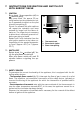
2. HYDRAULIC CONNECTION
2.1.
Connection to the water distribution
mains must be realised using a 3/
4”G tube. The cold water inlet is on
the right whereas the outlet is on
the left (facing the appliance).
2.2 The appliance must mount the re-
lief-safety hydraulic valve (provided
with every appliance) on to the wa-
ter inlet piping. The valve must not
be tampered with.
2.3 Run the water for some time, en-
suring there are no foreign bodies
inside the piping like metal chip-
pings, sand, cloth and other. Should
such bodies enter the relief-safety
hydraulic valve, the functioning
would be jeopardised causing, in
some cases, its breaking.
2.4 Ensure that the pressure of the wa-
ter supply system does not exceed
the value of 8 bar. In case of hi-
gher pressure, an excellent quality
pressure reducer must be used,
mounted away from the applian-
ce. In this case, the hydraulic val-
ve must never drip during heating.
Dripping must also be checked
when a single direction stop cock is
applied upstream of the valve.
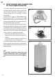
2.5. Avoid the dripping of the valve falls
on to the water heater.
Apply the valve as in fi g. 3, envisio-
ning a small collection funnel (drip)
connected to the drain.
2
20 cm.
Carry out the installation as to standards.
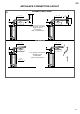
STANDARDS FOR INSTALLATION
1.1. Position the appliance near the
chosen wall so that the two inlet
and outlet pipes are parallel to it.
1.2 Should the water heater be installed
in the corner between two walls,
1. POSITIONING
keep suffi cient distance between
the wall and the appliance for the
installation and dismantling of the
components.
Nota:
lo svuotamento completo si realizza per sifo-
naggio. Collegare un tubo fl essibile al rubi-
netto di scarico come riportato in fi g. 2.