
Installation and Use


83
GB
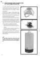
5. GAS CONNECTION
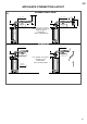
4. CONNECTION TO FLUE
3.1. The connection of the gas piping to the
valve must happen with 1/2” G pipe.
5.2 We recommend the insertion of a stop
cock before the gas unit.
Note: for the connection strictly comply
with the regulations in force.
4.1. by means of a tube of suitable diame-
ter to the L int diameter (overall dimen-
sions table fi g. 1) inserted on the ap-
pliance hood.
4.2 It is important that the fl ue has a good
draft.
4.3 Avoid long horizontal passages, in-
clined plane and throttling inside the
evacuation duct as they can cause bad
combustion.
4.4 Should the drain pipe cross cold pre-
mises, unheated, envision a thermal
insulation to avoid the forming of con-
dense.
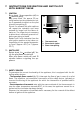
4.5 In no case must the fumes hood be eli-
minated, amended or replaced as it is
integral part of the entire combustion
system of the gas water heater.
4.6 The correct installation of the fumes
discharge pipe is the exclusive respon-
sibility of the installer.
The device must not be removed for any reason; in case of malfunctioning
of the fl ue, the combustion products and, therefore, the carbon monoxide
also, may fl ow into the premises, causing a serious danger for the occu-
piers.
For the same reason, in case of defect, the replacement with original spa-
re parts must be carried out only and exclusively by qualifi ed staff , being
careful to correctly position the various components.
5
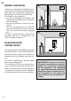
NO
SÌ
NO
NO
ATTENTION!
For the correct functioning of the gas appliances, the fumes hood must be perfectly
positioned. Avoid any other type of installation like in the examples reported at the side: