
Installation and Use


92
GB
3
4
2
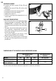
NOZZLES CHANGE
a) Loosen the main nozzle 10 (fi g. 16) and
replace it.
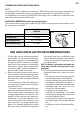
b)Replace the nozzle 3 (fi g. 19) of the pilot
as follows:
• completely loosen the fi xing screw 2.
• completely loosen the fi tting 4.
• replace the nozzle 3.
• re-mount carrying out the operations in re-
verse order.
GAS UNIT RE-MOUNTING
• Re-mount the unit by carrying out the ope-
rations indicated in paragraph “GAS UNIT
DISMANTLING”, in reverse order. Carry out
the following checks before any other ope-
ration:
• The gas valve thermostat probe must be
fully inserted in appropriate sheath and
the probe locking spring must be hooked
to the same sheath.
The correct setting of the burner is the
specifi c responsibility of the installer.
• Check that, by removing and re-mounting
the gas unit, the components are correctly
positioned.
18
19
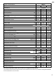
DIMENSIONS OF THE NOZZLES HOLES EXPRESSED IN MM
MAIN BURNER NOZZLE
10 (FIG. 16)
PILOT BURNER NOZZLE
3 (FIG. 19)
MODELS
120 150 200 120 -150 -200
METHANE GAS (G20)
1,85 - 3,00 1,95 - 3,00 2,15 - 3,40 0,37
LIQUID GAS (G30 G31)
Butane and Propane
1,62 1,75 1,90 0,24
On the nozzles the above values are reported in cents of a millimetre.