
Technical data


19
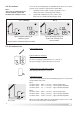
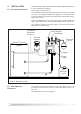
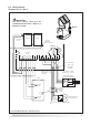
FIG. 6.4A WIRING DIAGRAM - STANDARD SYSTEM
12
S1
34
S2
56
S3
78
S4
Temp. Sensor
Pt1000
12
N
14
15 16 17
R2
18
NR1
20
NL
FUSE 4A
19
13
L
N
SOLARcomfort Pump
(Pump Module)
brown
g/y
blue
brown
g/y
blue
brown
g/y
blue
g/y
g/y
blue
brown
blue
brown
FUSE 5A
Mains Supply
220-240V
Cylinder
S3 Upper
Sensor
S2 Lower
Sensor
S1 Collector
Sensor
Collector Collector
S4 Energy
Monitoring
Sensor (option)
BS 1383/A kite marked
Domestic Plug - fused 5A
or
Double Pole Isolating
Switch fused 5A (as shown)
Cylinder
Manual Reset
Overheat
Stat NC
R1 2(1)A 220-240V~
1.0mm² 3 core heat resistant flex 3093y
1.0mm² 3 core
heat resistant
flex 3093y
1.0mm² 3 core
heat resistant
flex 3093y
6.4 WIRING DIAGRAM
STANDARD SYSTEM - Arr 1
Arr 1
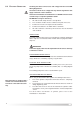
IMPORTANT
The mains supply cable must be
separated from the sensor cables by a
minimum of 15mm.