
Operating Instructions and Installation Instructions

GB
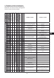
C
D
B
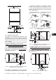
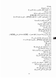
50 cm
5 cm
E
E
A
Picture 6 - Installation values
2.2.c. HORD horizontal model
This appliance is designed to be fitted to the wall
horizontally, with the two fixing brackets attached
to the wall (Picture 7-8). It can also be installed on
the floor or the ceiling if necessary, using a set of
straps (optional).
In this situation, please consult the installation
instructions supplied with the set of straps.
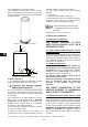
HORDroit version with water inlet and outlet
pipes on the protection element
The model is already prepared at the company so
that it can be installed horizontally onto a wall; the
supply pipes are located on the right-hand side of
the appliance (Picture 7).
E
E
C
A
B
D
50 cm
Picture 7 - Horizontal element on the protection element
- supply pipes on the right-hand side
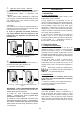
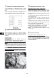
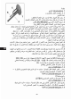
If the pipes are positioned on the left-hand side,
it is absolutely fundamental that the electric base
is removed to position the immersion heating
element in the lower part of the appliance. Invert
the blue and red piping reference clips (Picture 8
and 9). Hot water connection must be performed
on the upper piping.
Picture 8 - Heating element assembly for left-hand side
models HORD
E
E
C
A
B
D
50 cm
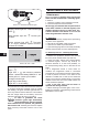
Picture 9 - Horizontal element on the protection element -
supply pipes on the left-hand side
HORBas HORB version with water inlet and
outlet pipes on the bodywork ring nut
This appliance is designed to be fitted to the wall
horizontally; the supply pipes are located at the
base (Picture 10).
A
E
C
D
B
E
Picture 10 - Horizontal model on ring nut
A : Hot water / B : Cold water / C : Safety assembly / D : Shut-off valve / E : Dielectric connection
51