
Installation Instructions

50
CS175-275-575-875 Installation Guide
11 PROGRAMMING MODULES AND LOCATIONS
11.1 Parts of the system
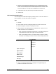
The system is divided into modules, locations, segments and bits. The control panel is
one module. Each module contains locations, which in turn, contain one or more
segments. Each segment has between one to eight bits of programmable data. See
Programming
on page 56 for a list of locations.
11.2 Programming data
The segments in each location contain the same type of data. This can be either
numerical or feature selection data.
11.2.1 Numerical Data (ND)
Numerical data is programmed by entering a number from 0 to 255 using the keypad
keys.
On an LCD keypad, the number in the location is displayed. For locations with a maximum
of 15, for example the phone prefix in Location 1, the hexadecimal equivalent is displayed
in parenthesis.
10 = 10(A) 12 = 12(C) 14 = 14(E)
11 = 11(B) 13 = 13(D) 15 = 15(F)
On an LED keypad, the LEDs for zones 1 to 8 are utilised and the numeric equivalents of
their illuminated LEDs are added together to determine the data in a programming
location. The numeric equivalents of these LEDs are as follows:
Zone 1 LED = 1 Zone 5 LED = 16
Zone 2 LED = 2 Zone 6 LED = 32
Zone 3 LED = 4 Zone 7 LED = 64
Zone 4 LED = 8 Zone 8 LED = 128
11.2.2 Feature Selection Data (FSD)
Feature selection data displays the current condition (on or off) of eight features
associated with the programming location and segment selected.
On the LCD keypad, the numbers of the enabled features are displayed. If a feature is not
enabled, a hyphen is displayed instead. Several features can be selected from within one
segment. Enter the feature number of the segment on the keypad to turn the feature on or
off.
On the LED keypad, the number of the enabled features is displayed by the
corresponding LEDs.
•
Press any numeric key between 1 and 8 to select a feature. The corresponding LED
lights up (feature on).
•
Press the number again to turn the feature off. The LED goes out (feature off).