
Installation Instructions


92
CS175-275-575-875 Installation Guide
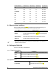
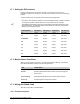
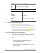
Module Number DIP Switch 1 DIP Switch 2 DIP Switch 3 DIP Switch 4
34
On On On Not Used
33
Off On On Not Used
32 (Default)
On Off On Not Used
39
Off Off On Not Used
38
On On Off Not Used
37
Off On Off Not Used
36
On Off Off Not Used
35
Off Off Off Not Used
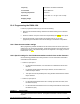
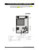
16.2 Module status conditions
When you apply power to the CSx75, the middle LED (red) should start blinking. The
following table defines the different states of the red and yellow LEDs.
LED Module Status
Red blinking
Red off
Normal data communication with the CSx75.
No data communication with the CSx75. Check the wiring and
power source.
Yellow blinking
Yellow off
Receiving radio signals from learn mode wireless sensors.
No radio signals currently being received.
"
The red LED at the bottom of the module may emit a dim glow but is not used as an
inidicator and can be ignored.
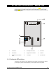
16.3 Wiring the RX8i4-16i4
Wire the bus according to the table below.
16.3.1.1
Terminal description
Terminal Description
Power
Connect to the KP POS terminal of the CSx75. Current draw is 30 mA.
Gnd
Connect to the KP GND terminal of the CSx75.
Data
Connect to the KP DATA terminal of the CSx75.
16.3.2 Specifications
Operating power
12 VDC supplied from CSx75
Compatibility
Compatible with CS175-275-575-875