FP/FR1100/1200/ 2000 Series Analogue addressable fire panels, repeaters and emulators Installation and Commissioning Manual Revision 6.
ARCNET is a registered trademark of Datapoint Corporation. Aritech is an Interlogix company. www.aritech.com COPYRIGHT © 2001 Interlogix B.V.. All rights reserved. Interlogix B.V. grants the right to reprint this manual for internal use only. Interlogix B.V. reserves the right to change information without notice.
CONTENTS 1 INTRODUCTION ............................................................................................................................................ 4 2 GENERAL INFORMATION ............................................................................................................................... 5 2.1 Product codes ..................................................................................................................................... 5 2.2 Design specifications...........
6.7.2 7 FP/FR1xxx............................................................................................................................ 50 COUNTRY DEPENDENT SELECTIONS ............................................................................................................ 51 7.1 Language selections ......................................................................................................................... 51 7.1.1 FP/FR1xxx............................................................
LIST OF FIGURES Figure 1: Figure 2: Figure 3: Figure 4: Figure 5: Figure 6: Figure 7: Figure 8: Figure 9: Figure 10: Figure 11: Figure 12: Figure 13: Figure 14: Figure 15: Figure 16: Figure 17: Figure 18: Figure 19: Figure 20: Figure 21: Figure 22: Figure 23: Figure 24: Figure 25: Figure 26: Figure 27: Figure 28: Figure 29: Figure 30: Figure 31: Figure 32: Figure 33: Figure 34: Figure 35: Figure 36: Figure 37: Figure 38: Figure 39: Panel dimensions ..........................................................
1 INTRODUCTION The purpose of this manual is to provide assistance during the installation and commissioning of the FP/FR1100/1200/2000 Series fire panels, and repeaters/emulators. Please note that the manual is intended as a guide only and is not to be used to replace any local building and/or wiring codes. Other manuals available are: 1. Aritech 900 Series Detectors Installation Manual 2. Aritech 2000 Series Detectors Installation Manual 3. FP1200/2000 Reference Guide 4.
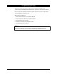
2 GENERAL INFORMATION 2.1 Product codes FIRE PANELS: Firepanel Max. nr. of zone cards Max. nr. of loops Max. nr. of detectors / loop Default detector Internal printer Cabinet Size (mm) Approx.
Repeater/ Emulator Panel Max. nr. of zone cards Internal printer Cabinet Size (mm) Connected to FP1200/ 2000 Voltage Source Approx. weight (kg) (without batteries) FR832 N/A No 516x346x80 Current Loop 230V DC 8 FBP700-D 0 No 240x320x60 LON2000 24 VDC 1.5 FBP700-S 0 No 240x320x60 LON2000 24 VDC 1.5 FRL700 0 No 240x320x60 LON2000 24 VDC 1.5 RP2032 0 No 397x290x64 Current Loop 24 VDC 3 UN2000 0 No 290x145x80 NC/NE2011 230 VAC 1.
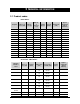
Compatibility with Extra Modules ZE2064 Description FP1216 FP1216EN/ 2416/2432/ 2864 FP1264 / 2464/ 24128/ 28255 64 zones LED extension FB2x00 FR1200 FR2000 / 2032/ 2064 • FR2012 8/ 20255 • * Excludes the FP1200 series of firepanels ** Option on FP2416/2464, FP2864/28255 & FR20255 only MODULE VARIATION: Board Product used in Variation FEP1200 FP11xx/12xx FEP1200 – 0 x Auxiliary inputs FEP2000 FP2xxx/FB2x00 FEP2000 – 4 x Auxiliary inputs FC1200 FP11xx/12xx & FR12xx FC1200 – 1 x DB9 port
8 • Fault/disablements from addressable points • Output to fault warning routing equipment • Standardised input/output interface (according to DIN 14661) • Test condition • Total loss of power supply (option) FP/FR1100/1200/2000 V6: Installation and Commissioning Manual
3 TECHNICAL SPECIFICATIONS 3.1 General specifications Loop capacity: • Every loop PCB (LC2002) can be configured as two class A loops or four class B loops.
• Fire brigade indicators Signal Delay On Delay Off Fault/Disable Stop fire brigade • • - 1 x LED - Red - 1 x LED - Amber - 1 x LED - Amber - 1 x LED - Amber - 1 x LED - Amber Zone monitoring indicators Fire - Fault - 16/64 x LED - Red (expandable to 32/128, 48/192 or 64/255) 16/64 x LED - Amber (expandable to 32/128, 48/192 or 64/255) Indicators related to network facilities All Panel - 1 x LED - Amber - 1 x LED - Amber Membrane keyboard: 1, 2, 3, 4, 5, 6, 7, 8, 9, 0, A ..
Tamper switch (FP2000 Range only): Fitted to the inside of the fire panel door to record any entry to the cabinet. Third source (when implemented on the FP2000 range only): Test button and LED to test total loss of power supply.
Standard Outputs FP/FR1xxx & FR2000 FP1216EN & FP1264 FP/FR2xxx (All standard outputs are located on the sounder board.
Power Supply Characteristics Fuses Maximum current drawn from the primary input Maximum output ripple voltage Fault Relay (Configuration depended on jumper setting – refer to section 6.4.2.2.) FP/FR1xxx & FR2000 FP1216EN & FP1264 FP/FR2xxx - Battery flat - Battery flat - Battery flat - Flat battery cut-out - Flat battery cut-out - Flat battery cut-out - Earth fault - Earth fault - Auxiliary supply fault - Auxiliary supply fault AC fuse – 0.
3.2.
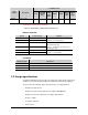
3.2.5 Environmental Environmental FP/FR1xxx & FR2000 FP1216EN & FP1264 FP/FR2xxx Enclosure protection IP54 IP54 IP54 Temperature Operational: -5 ºC to +40 ºC Operational: - 5 ºC to +40 ºC Operational: - 5 ºC to +40 ºC Storage: -20 ºC to +60 ºC Storage: -20 ºC to +60 ºC Storage: -20 ºC to +60 ºC 4 MOUNTING INSTRUCTIONS 4.1 FP/FR12xx 4.1.1 Panel dimensions Figure 1: " Panel dimensions All dimensions are in mm.
4.1.2 Mounting instructions Figure 2: Top/bottom cable entries 1. Panel front A. Bottom view 2. Rear mounting surface B. Top view 3. Panel top C. Rear panel view 4. Panel bottom 1 5. Cable entries 20 mm 2 440 mm for the FP1216EN & FP1264 Not applicable to FP1216EN & FP1264 6.
CAUTION! Mains wires (230 V) must enter the cabinet from the right bottom hole in the cabinet only. Top entry violates IEC950 safety requirements and will cause EMC problems. Mains wires must not be routed past the electronic modules in the rear of the panel. It must be kept as short as possible and routed directly to the mains input. 4.1.3 Panel & repeater layout Figure 3: Panel layout A. FP1216EN & FP1264 16. Host CPU board B. FR1200 & FR2000 17. DB-9 port 1. Transformer 18.
4.2 FP2xxx 4.2.1 Panel dimensions Figure 4: " 18 Panel dimensions (cabinet size A) Cabinet size B: 804 x 441 x 109 mm (H x W x D) Cabinet size C: 473.
4.2.2 Mounting instructions Figure 5: Mounting instructions A. Cabinet size A C. Cabinet size C B. Cabinet size B 1. 4 x 5 mm mounting holes The 5 mm mounting holes are located as shown in Figure 2. Five 20 mm holes are provided for cable entry at the top and bottom of the panel.
The total panel weight equals: 11 kg for size A cabinet (excluding batteries) 15 kg for size B cabinet (excluding batteries) 9 kg for size C cabinet (excluding batteries) Figure 6: Cable entries CAUTION! Mains wires (230V) must enter the cabinet from the left bottom hole in the cabinet only. Top entry violates EN60950 (IEC950) safety requirements and will cause EMC problems. Mains wires must not be routed past the electronic modules in the rear of the panel.
4.2.3 Panel layout Figure 7: Panel layout 1. Numeric keypad 15. 2 x battery 2. Common LED board 16. Power supply and battery charger 3. LCD Display and backlight board 17. Modem (optional) 4. Host processor board 18. Optional ARCNET network card 5. Current loop terminal connections 19. Host power supply board 6. RS232 ports (DB-9connectors) (port 1-front; port 2-back) 20. Bus-termination card 7. DB9-DB25 adapter (with modem) 21. DIP switch 8. Front-end processor board 22.
4.2.4 Repeater layout Figure 8: Repeater layout 1. Numeric keypad 10. Bus-termination card 2. Common LED board 11. DIP switch 3. LCD Display and backlight board 12. Zone matrix display board 4. Host processor board 13. Optional internal printer (PR2000) 5. Current loop terminal connections 14. Service/commission mode switch 6. RS232 ports (DB-9 connectors) (port 1-front; port 2back) 15. Non-volatile memory lock 7. 24 VDC power supply 16. Memory back-up battery jumper 8.
5 LOOP DESIGN (FP12XX/FP2XXX/FB2X00 ONLY) 5.1 Typical configuration The fire panel accepts the following loop configurations.
Figure 11: Class "B" Single direction loop (Star configuration) Figure 12: Class B single direction loop with tee offs A maximum of 126 detectors (900 Series) or 128 detectors (2000 Series) can be connected to a loop. For combinations of fire sensing devices, monitoring controllers and input/output devices, the maximum number of addressable units must be calculated. Please refer to the Installation Manual of the 900 Series and 2000 Series detectors.
5.2 Suitable cable types The maximum serial cable resistance must be no more than 100 ohm and the maximum loop capacitance in parallel with this should not exceed 1uF. This will ensure that 126 (900 Series) or 128 (2000 Series) detectors can be operated over a distance of 2 km. " The cable resistance limit is calculated to maintain the minimum required supply - voltage in the presence of the worst-case load conditions.
6 FIELD CONNECTIONS 6.1 Loop, output and input connections 6.1.1 FP12xx Figure 13: 26 Position of inputs, loops and relay connections 1. FEP 9. Fire alarm devices 2. Power supply board 10. General input (FP1216/64 only) 3. Loop driver 11. Fault routing return input FP1216/64 only) 4. Sounder board 12. Fire protection return input (FP1216/64 only) 5. Programmable relays (FP1216/64 only) 13. Fire brigade return input (FP1216/64 only) 6. Fault routing (FP1216/64 only) 14.
6.1.2 FP2xxx Figure 14: Position of inputs, loops and relay connections 1. FEP 9. Fire alarm devices 2. Power supply board 10. General input 3. Line driver 11. Fault routing return input 4. Sounder board 12. Fire protection return input 5. Programmable relays 13. Fire brigade return input 6. Fault routing 14. 2 x class A loops or 2 x class B loops 7. Fire protection 15. 4 Auxiliary inputs 8.
6.2 Connections 6.2.1 Loop connections Standard, the panel is configured in a class A set-up (see also Chapter 5, Loop design): Figure 15: Class A loop connection 1. Forward 3. Loop 1 2. Return 4. Loop 2 When class B operation is required, the A-jumpers should be removed to double the amount of loops. The B-jumpers should be put in. If 8 A class loops are in use and the Bjumpers are put in only the first 8 loops will be class B.
Figure 17: " Class B loop connection 1. Forward 3. Loop 1 2. Return 4. Loop 2 y The FWD and Return of each class A loop used must be linked in the correct polarity y Isolators are polarity dependant (see Detector Installation and Commissioning Manual) y Preferably loop boards must be configured for class A y A and B loops can be combined in the following way: a) Configure as class A b) Class B loops are connected as follows: Figure 18: Class AB loop connection 1. Forward 3. Loop 1 2.
6.2.2 Programmable relay Each of the four programmable relays has a change over contact. The relay is shown in the NORMAL state. A red LED indicates the state of the relays. Figure 19: Programmable relay connections 1. Programmable relay 4 (Out8) 7. Output 6 switched LED indication 2. Programmable relay 3 (Out7) 8. Output 5 switched LED indication 3. Programmable relay 2 (Out6) 9. Common 4. Programmable relay 1 (Out5) 10. Normally closed (Relay shown in NORMAL state) 5.
6.2.3 Supervised outputs A These outputs provide 24 VDC when active. A red LED displays the state of the outputs. (Refer to sections 3.2.1 and 3.2.3 for technical information on these outputs.) Figure 20: Supervised relay output’s connection on SD2000 common I/O board 1. Fault routing (Out4) 3.
J5 out J5 in OUT 4 (Refer to positions 6 in figure 13.) The configurations for OUT 4 are shown below (FAIL-SAFE). The switch is closed when there is a fault. The LED is ON when there is no fault. Figure 22: Two configurations for relay output 4 B Outputs Fault routing Figure 23: 32 CONFIG. 1 OUT4 CONFIG. 2 J6 in J6 out J7 out J7 in Location of jumpers on sounder board 1. Sounder board 6. Fire alarm device (Out1) 2. Programmable relays (A – Out8, B – Out7, C – Out6, D – Out5) 7. Input 8 3.
6.2.5 Supervised inputs IN5 - IN8 The supervised inputs are located on the sounder PCB. The function of these inputs is determined by the operation mode of the FP2000 (see Appendix B). In EN, NEN and EP operation mode these inputs have no dedicated function and are freely programmable through I/O logic. Figure 24: Supervised inputs connections 1. Input 8 3. Input 6 2. Input 7 4.
6.2.6 Auxiliary inputs (FEP2000 only) Four auxiliary inputs are provided on the FEP-PCB. Each input is opto-isolated and independent of polarity. These inputs are not supervised and can be used through I/O programming. Figure 25: 34 Auxiliary inputs 1. Auxiliary input 1 5. Section of FEP board 2. Auxiliary input 2 6. 20-28V DC or 10-15V AC 3. Auxiliary input 3 7. Field wiring 4. Auxiliary input 4 8.
6.2.7 Connection of dual tone siren AS263/AS264 The Aritech dual-tone siren can be connected on Sounder (out 1) and Fire Brigade (out 2) in the following way: Figure 26: Dual tone siren connections 1. Common 4. Out2 2. Sound 5. Out1 3. Sound Set jumpers as follows: " J2 in, J3 in, J18 in, J19 in This set-up should only be used when operation mode is "EP" (see Appendix B).
6.3 Communication port connections (all models) 6.3.1 Current loop A current loop output is provided as a standard feature on the FP2000 Series of fire panels. The current loop is used to drive up to 15 fireman’s panels and conventional repeaters. Each fireman’s panel/repeater has its own unique address, by means of resistor settings at that panel. Please refer to the appropriate Installation Manual for the correct settings.
6.3.2 RS232 ports The two RS232 ports are provided with DB25 male connectors. The location of the connectors is shown in Figure 3 & Figure 7. The signals at both the connectors are as follows: " PIN NR 1 2 3 4 5 6 7 8 9 Signal name DCD RXD TXD DTR GND DSR RTS CTS RI To route the RS232 cable inside the cabinet, refer to section 4.
6.4 Power supply connections 6.4.1 24 V version FR2xxx models The FR2000 is delivered with a 24 V connection board. Figure 28: 38 FP/FR2xxx power supply connections (24 V version) 1. 24 VDC termination board 4. Earth 2. +24 V 5. Charger fail (Normally shorted input) 3. –24 V 6.
6.4.2 230 V version (FP/FR1xxx/FR2000 models – except FP1216EN & FP1264) 6.4.2.1 Mains connection Figure 29: FP/FR12xx/FR2000 connecting mains-to-mains terminal block 1. Mains terminal block 5. To earth stud on panel 2. Neutral 6. To transformer 3. Earth 7. Mains disconnect with fuse 4. Live A mains terminal block with fuse is provided for connecting the panel to the mains. Please note the polarity of live, mains and earth.
6.4.2.2 Power supply connections Figure 30: FP/FR12xx power supply and fault relay connections 1. Black 7. Vin connection 2. Link 8. VR3 LCD contrast adjuster 3. Red 9. Modem (MOD2000) connection 4. 12 V Batteries 10. Start-up 5. Host CPU connection 11. Fault relay output 6. BAT connection 12.
6.4.2.3 Power supply connections 1. Ensure that the mains power is disconnected before opening the unit. 2. Connect the fault relay as shown in figure 31. 3. Route the wires away from sharp edges and corners and fix them into position. Figure 31: FP/FR12xx power supply’s fault relay connections 1. Normally open 3. Normally closed 2.
6.4.3 FP1216EN & FP1264 Power supply connections Figure 32: 42 FP1216EN & FP1264 power supply and transformer connections 1. Mains terminal block 10. Transformer (TRF1200) 2. Neutral 11. Power Supply (PS1200S77) 3. Ground 12. Vin 4. Live 13. Bat 5. Mains switch with fuse 14. Black 6. To ground stud on panel 15. Battery connection wire 7. Degrees C 16. Red 8. +Vout 17. 12 V Battery 9. –Vout 18.
6.4.4 230 V version (FP2xxx models) Figure 33: FP2xxx power supply and associated connections (230 V version) 1. 230 VAC 5. To M5 earth stud mounted on back panel 2. Live 6. 24 V power to ancillary fire panel equipment 3. Neutral 7. 12 V batteries 4. Earth The Direct Online power supply PSU-2000 has been designed according to EN54-4. A mains switch (on the bottom) is provided, as well as a battery ON/OFF switch.
Two 12 V batteries have to be put in series and connected to the battery terminals. No other equipment may be connected to the battery terminations. The PSU-2000 is designed for use in Aritech fire panel housing only. An optional third source battery (9 V, PP3) can be installed as a third source of power. The location of the third source battery is shown in Figure 7. " 44 Refer to Section 4 – Mounting instructions for routing of mains wires in cabinet.
6.5 Installing a modem The installation of the MOD2000 modem is described below. The modem is provided with a bracket for wall mounting. To install this bracket, please refer to Figure 3, Figure 7 and Figure 34. 1. Remove the protective cover from the double-sided self-adhesive tape on the rearmounting surface of the bracket supplied with the modem. 2. Position the mounting bracket inside the fire panel as shown in Figure 3 and Figure 7 and fix it into position using the double-sided self-adhesive tape.
Figure 34: Modem MOD2000 interconnection diagram 1. To 5 V on power supply (modem terminal) 8. To earth 2. 5 V to printer (not used – fixed in position to prevent contact) 9. Green 3. Telephone line adapter (if required) 10. Phone 4. To telephone line 11. Line 5. To Ser2 (DB-9 connector) 12. Line connector 6. Not used 13. Modem connector 7.
6.6 Network connections 6.6.1 NC2011/NC2051 ARCNET network cards The NC2011 and NC2051 are interface cards required to network FP2000 Series fire panels and FR2000 Series repeaters/emulators. All network nodes communicate via the ARCNET protocol, using RS485 electrical (NC2011) or optical medium (NC2051). Every node on the network - except the UN2000 - must have a network card installed as a standard. The PCB is delivered with the necessary washers, nuts and spacers to allow for proper mounting.
6.6.2 NE2011/NE2051 ARCNET network extension cards The NE2011 (RS485) and NE2051 (Optical) are network interface modules that are mounted directly on the NC2011 or NC2051 network card. The modules provide the user the ability to implement a wide range of network topologies when networking FP2000 Series fire panels and FR2000 Series repeaters/emulators. The modules are delivered with the necessary washers, nuts and spacers to allow for proper mounting.
6.6.3 FP/FBP/FRL700 Serial communication network (LON2000) The LON2000 interface module can be used on the following range of panels: FP2xxx, FP12xx, FP1xxx, FB2xxx and UN2011 series of products. (Please note that this module is not for use on any type of repeater e.g. FR2xxx series of products.) The LON2000 interface module provides the hardware platform for the above mentioned products to communicate to the FP700 range of serial communication interfaces.
6.7 LCD contrast 6.7.1 FP/FR2xxx The LCD display may be set to obtain maximum contrast by adjusting the viewing angle of the LCD display. This viewing angle is set by adjusting potentiometer VR 1 located on the LCD display and backlight board. Figure 39: Adjustment of the LCD viewing angle 1. LCD display and backlight board 6.7.2 2.
7 COUNTRY DEPENDENT SELECTIONS 7.1 Language selections 7.1.1 FP/FR1xxx Language selection is Software Selectable. Please refer to Appendix A 7.1.2 FP/FR2xxx The DIP switch on the inside of the panel is used to select the language. Please refer to Appendix A. SW1/SW2/SW3 determine the language. 7.2 Operation mode NEN, EN, VdS or EP mode of operation is selectable.
8 COMMISSIONING A FP2000 SERIES FIRE PANEL 8.1 Before switching on 1. Visually check the fire panel for any damage that might have occurred during installation. In particular, check for loose pieces that could have fallen in the electronics. 2. Check that all harnesses are securely plugged into the correct plug positions on the printed circuit boards. 3. Ensure that both the mains switch and the battery on/off switch are in the OFF position. 4.
8.2 Procedure for switching on 1. Switch the main power on at the power supply or connect the 24 V to the 24 V supply board. 2. The internal buzzer will sound and the product code will be displayed on the LCD screen along with the revision of host firmware, firmware code and the creation date of the firmware. If the above does not occur, DO NOT proceed. Check that the mains supply is present and that the fuses are good. 3. Switch the battery On/Off switch to the ON position (230 V model only). 4.
11. Investigate all devices that are reported Disabled. 12. Check all output relays for correct switching. 13. Configure your Panel ID. IF A NETWORK IS INSTALLED: 1. Configure network set-up with one of two methods: • Manually using LCD menus. • Program by means of a laptop computer using the RS232 port. 2. Investigate all panel and repeater faults that are reported. 3. Check status of the systems on the ARCNET network that are configured to communicate with the repeater.
APPENDIX A: DIP SWITCH SETTINGS ON HOST PSU BOARD (FP/FR2XXX) On host power supply board: SW1 SW2 SW3 SW4 SW5 SW6 SW7 SW8 OPTION ON Aritech (950 Series) OFF Sentrol (2000 Series) OFF OFF OFF ON EN Operation VdS Operation ON OFF NEN Operation ON ON EP Operation Language Group 1 2 3 OFF OFF OFF English English English OFF OFF ON Italian Lithuanian Lithuanian OFF ON OFF Dutch (Belgium) Polish Danish OFF ON ON Portuguese Hungarian Swedish ON OFF OFF Dutch (Ho
APPENDIX B: SOFTWARE SELECTABLE OPTIONS (FP/FR1XXX) OPTION 1 Aritech 900 Series 2 Aritech 2000 Series 3 EN Operation 4 Vds Operation 5 NEN Operation 6 EP Operation * Lang. Gr.1 * Lang. Gr2 * Lang. Gr.
APPENDIX C: OPERATION MODES Mode SOUNDERS: EN VdS* NEN EP Sound Silence Delay Resound (level 2) Silence (level 2) Allowed Resound (level 2) Silence (level 2) Allowed Resound (level 2) Silence (level 1) Not allowed 1 min.
3252-6.