
Installation Instructions


FP/FR1100/1200/2000 V6: Installation and Commissioning Manual 37
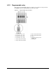
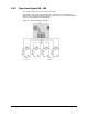
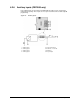
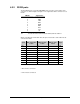
6.3.2 RS232 ports
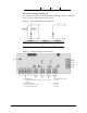
The two RS232 ports are provided with DB25 male connectors. The location of the
connectors is shown in Figure 3 & Figure 7. The signals at both the connectors are as
follows:
PIN NR Signal name
1 DCD
2 RXD
3 TXD
4 DTR
5 GND
6 DSR
7 RTS
8 CTS
9 RI
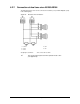
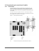
" To route the RS232 cable inside the cabinet, refer to section 4.
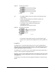
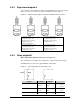
When connecting the null-modem cable, the pins on both sides of the cable must be
connected as follow:
Signal DB25 (Panel Side) -
Female
DB25 (PC Side) -
Female
DB9 (PC Side) -
Female
Signal
TXD 2 3 2 RXD
RXD 3 2 3 TXD
RTS 4 5 8 CTS
CTS 5 4 7 RTS
DSR 6* 20 4 DTR
DTR 20 6** 6*** DSR
DCD 8* 8** 1*** DCD
RI 22* 22** 9*** RI
GND 7 7 5 GND
* Pins must be connected
** Pins must be connected
*** Pins must be connected