
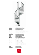
Installation Guide

6 - ck
English
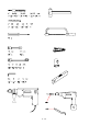
Before starting the assembly process, unpack all components of the staircase. Lay them out on a large surface and
check the quantity of all the pieces, by consulting the table (TAB.1: A = Code, B = Quantity).
Inside the staircase box you will also nd a DVD which we suggest watching before proceeding to assemble.
For the USA only: call the customer support line at 1-888 STAIRKT, should you have any case of need.
Preliminary Assembly
1. Screw the parts D32 and D33 into the treads (L02) (g. 2).
2. Carefully measure the oor-to-oor height and determine the required number of spacers (D03) (TAB.2).
3. Assemble the spacers (D14, D03, D02) together in one piece. Do the same for the spacers (D04, D03, D02)
(g. 1).
4. Assemble the parts C63, C65, C66 into the baluster (C03) (g. 3).
5. Assemble the parts B72, B73, B74, B78 into the landing E03, without tightening (g. 7).
6. Assemble the base G03, B17 and B46 (g. 1).
Assembly
7. Determine and mark on the oor the centre of the hole, then position the base (G03+B17+B46) (g. 4).
8. Drill with 14 mm (
35
/
64
”
) drill bit and x the base (G03+B17+B46) into the oor by means of the parts B13 (g. 1).
9. Screw the pole (G02) into the base (G03+B17+B46) (g. 1).
10. Insert the spacers (D14+D03+D02) (g. 5).
11. Insert the base plate cover (D05) (g. 5).
12. Insert the rst tread (L02) into the pole (G02). Then continue with the assembly, by adding alternatively one
spacer (D04+D03+D02) and one tread (L02). At this stage we suggest to position the treads alternately one to
the right and one to the left, in order to distribute the weight in a balanced way (g. 5).
13. When you reach the end of the pole (G02), screw the part B47 on it, then add the second pole (G02) and
continue with the stair assembly (g. 5).
14. When you reach the end of the pole (G02), screw on it the part B46 and the part G01. (Screw the part G01, until
its upper end sticks out approximately 15 cm (5
29
/
32
”
) from the stair height (g. 6). Continue adding the treads,
by using the part D01 inserted into the spacers (D04+D03+D02).
15. Finally add the stair landing (E03). Fasten the parts B05, B04 and screw the part B03 sufciently (g. 1) but
keeping in mind that the treads still have to be rotated to their nal position and that the points A and B of the
landing (E03) have touch the oor (g. 8).
Fitting of the Landing
16. Screw the part B71 into the element B74, making it run till the end. Insert the parts B75, B76, B75 - in this
order – and then again the element B71, without tightening too hard (g. 7).
17. Approach the part B76 to the ceiling. Determine the position, then drill with 14 mm (
35
/
64
”
) drill bit and x
completely by using the part B58 (g. 7).
18. Screw the lower part B71 till the points A, B and C touch the oor (g. 8).
19. Block the upper part B71 on the part B76 (g. 7).
20. Finally, block the part B73 (g. 7).
Assembly of the Railing
21. Spread-out the treads (L02) fan-like, after having chosen the rotation direction. The stair is now ready to use.
22. Starting from the landing (E03), insert the longer railing balusters (C03 - H 1190 mm - 46
7
/
8
”
), that build the
connection between the treads. Face them with the part C63 showing the part with the holes turned upwards
(g. 10). Tighten only the part B02 of the lower tread (g. 2).
23. Check very carefully the vertical position of the inserted balusters C03. This control is very important for insuring
the best results.
24. Tighten the part B03 completely (g. 10).
25. Tighten the part B02 of the upper treadcompletely (g. 2).
26. Check once more the vertical position of the railing balusters (C03) and, if necessary, correct it, by repeating the