
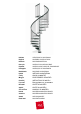
Installation Guide

7 - ck
previous operations.
27. Set the rst baluster (C03 - H 1190 mm - 46
7
/
8
”
) together with the reinforcing part (F07). Cut one long baluster
(C03 - H 1190 mm - 46
7
/
8
”
) to obtain the same size as all others you assembled previously.
28. Fix into the oor in relation to the rst baluster (C03), the part F01, by drilling with 8 mm (
5
/
16
”
) diameter bit. Use
the parts B11, B12, B83 and B02 (g. 1).
29. Find the handrail piece marked with letter “M” (A22) and the one with letter “R” (A23) which will be used for the
railing of the landing (E03) (g. 11).
30. Start to model the handrail pieces (A22) marked with “M”, in order to give it the handrial staircase’s shape most
alike (g. 1).
31. Beginning from the baluster (C03) on the landing (E03), start to x the handrail (A22),that you have already
slightly bent in the previous operation. Use the parts C64.
32. Connect all other handrail pieces (A22), by screwing, glueing and shaping them. Use the parts B33, D72 and the
glue (X01).
33. When you reach the rst baluster (C03) at the bottom of the stair, cut the excess piece of the handrail with a
hacksaw.
34. Complete the handrail (A22) by assembling the part A37. Use the parts C64 and the glue (X01) (g. 1).
35. Fit all remaining railing balusters into the treads (L02), tighten the part B02 and x to the handrail (A22), paying
attention to the vertical position (for the stairs with a diameter larger than 140 cm (55
1
/
8
”
), we suggest that you
rst assemble the shorter balusters) (g. 12).
36. Check again the regular shape of the handrail (A22) and, if necessary, correct it with a rubber hammer.
37. Complete the railing assembly by tting the parts B82 into the lower part of the balusters (C03) (g. 1).
Assembly of the Balustrade
38. Screw the baluster (C04) into the part G01 that sticks out from the landing (E03) (g. 10).
39. Assemble the parts F01 into the holes of the landing (E03), using the parts B07, B06, B23 (g. 1).
40. Position the shorter balusters (H. 935 mm - 36
13
/
16
”
) and tighten the part B02 (g. 1).
41. Fix the part A36 into the baluster (C04), by using the part B02 (g. 1).
42. Fix the handrail (A23) marked with the letter “R”, using the parts C64 (g. 1).
43. In case there were walls around the stair and depending on their position, it could be necessary to set one or
two more balusters (H. 935 mm - 36
13
/
16
”
) (g. 12).
44. In that case it is necessary to consider either the distance between all other balusters, or otherwise the
distance from the wall. For the xing it is suggested to drill the landing (E03) with 9 mm (
23
/
64
”
) diameter bit and
to use the xing parts F01, B02, B07, B06, B23. Whereas for the xing into the oor it is suggested to drill with
the 12 mm (
15
/
32
”
) drill bit and to use the parts F01, B02, B87 (g. 13).
Final Assembly
45. In order to tighten the staircase at the intermediate points, you must x into the wall the parts F09 and connect
them to the balusters (C03) by using the part F08. Drill the wall with a drill bit 8 and use the parts C50, C49,
B11, B12 (g. 14).
46. Stick the panels (H01) to the treads (L02) using the part B96 (g. 1).
47. Stick the panels (H03, H04), to the landing (E03) using the part B96 (g. 1).
After you have nished assembling the staircase,
please visit our website and send us your suggestions: www.arke.ws