
Installation Guide


4 - kl
English
WARNING: Carry out the installation in a “workmanlike” manner, strictly following the installation instructions and using
suitable tools. Always consult your local building department for code requirements that must be respected depending
on its destination of use (private, secondary, public…).
Before starting the assembly process, unpack all components of the staircase. Lay them out on a large surface and
check the quantity of all the pieces, by consulting the table TAB.1 (A = Code, B = Quantity).
For customers in the USA there is a customer assistance number 1-888 STAIRKT, which you can telephone in case
of problems.
Preliminary Assembly
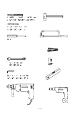
1. Assemble the parts C24, C25 and B20 to the treads (L03) (g. 2).
2. Carefully measure the oor-to-oor height and determine the required number of spacers (D08) (TAB.2) and
prepare them onto their proper spacer (D15) (TAB2)
3. Assemble the parts C63, C65, C66 onto the baluster (C03) (g. 3).
4. Assemble the base G03, B17 and B46 (g. 1).
Assembly
5. Determine and mark on the oor the centre of the opening, then position the base (G03+B17+B46) (g. 4).
6. Drill with 14 mm (
35
/
64
”
) drill bit and x the base (G03+B17+B46) into the oor by means of the parts B13 (g. 1).
7. Screw the pole (G02) into the base (G03+B17+B46) (g. 1).
8. Insert the base plate cover (D12) into the pole (G02) (g. 5).
9. Insert the spacers (D08), then the shorter spacer (D14), the spacers (D08), the rst tread (L03) with the wooden
staves parallel to the specied ascending side (g. 5A), the spacers (D08), the spacer (D15), the spacers (D08)
and another tread (L03) and so on. Add alternatively the treads alternately one to the right and one to the left,
so as to distribute the weight in a balanced way (g. 5).
10. When you reach the end of the pole (G02), screw the part B47 on it, then add the second pole (G02) and
continue with the stair assembly (g. 5).
11. When you reach the end of the pole (G02), screw on it the part B46 and the part G01. (Screw the part G01, until
its upper end sticks out approximately 15 cm (5
29
/
32
”
) from the stair height (g. 6). Continue adding the treads,
by using the part D01 inserted into the tread (L03).
12. Finally add the stair landing (E02). After having chosen the stair rotation (g. 7), position the landing (E02) with
the small hole (which is needed for the baluster passage (C03)) on the arrival side of the treads (L03) (g. 8)
Cut the landing (E02), if necessary, in relation to the oor opening.
13. Insert the parts B05, B04 and screw the part B03 sufciently (g. 1) but keeping in mind that the treads still
have to be rotated (g. 1).
Fitting of the Landing
14. Approach the part F12 to the oor. Determine the position, maintaining a distance of about 15 cm (5
29
/
32
”
) from
the external side of the landing (E02), pierce with a 14 mm (
35
/
64
”
) drill bit and x securely by using the part B13
(g. 1).
15. Fix the parts F12 to the landing (E02), by using the parts C58 (pierce the landing (E02) with the 5 mm (
35
/
64
”
) drill bit.
16. Position the parts B95.
Assembly of the Railing
17. Spread-out the treads (L03) fan-like. It is now possible to use the stair.
18. Starting from the landing (E02), insert the longer railing balusters C03 (H. 1190 mm - 46
7
/
8
”
), that build the
connection between the treads (L03). Keep the balusters C03 (H. 1190 mm - 46
7
/
8
”
) with the part C63 and the
pierced part to the top (g. 8). Tighten only the part B20 of the lower tread (g. 2).
19. Check very carefully the vertical position of the inserted balusters C03. This control is very important for insuring
the best results.
20. Tighten securely the part B03 (g. 8).
21. Tighten securely the part B02 of the upper tread (g. 2).
22. Check once more the vertical position of the railing balusters C03 (H. 1190 mm - 46
7
/
8
”
) and, if necessary,
correct it, by repeating the previous operations.
23. Position the rst baluster C03 (H. 1190 mm - 46
7
/
8
”
). Cut one long baluster C03 (H. 1190 mm - 46
7
/
8
”
) to