
Installation Guide
6 - kr
English
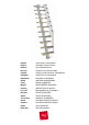
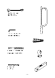
Before starting the assembly process, unpack all components of the staircase. Lay them out on a
large surface and check the quantity of all the pieces, by consulting the table TAB.1 (A = Code, B =
Quantity).
Inside the staircase box you will also nd a DVD which we suggest watching before proceeding to
assemble.
For customers in the USA there is a customer assistance number 1-888 STAIRKT, which you can
telephone in case of problems.
Assembly
1. Carefully measure the oor-to-oor height.
2. Calculate the rise:
1) subtract 22 cm (8 1/2”) from the oor-to-oor height you measured,
2) divide this value by the rises number minus one.
Example: for the measured oor-to-oor height of 268 cm and a staircase with 12 rises;
(268-22)/(12-1)=22,36 (8’3 1/2” 8 5/8”)/(12-1)=8 3/4”.
3. Determine the position of the support N19 (g. 1) keeping in mind two points:
1) the rise, calculated previously, also contains the tread depth (L40) (g. 2).
2) Position the support N19 keeping in mind the opening feature (g. 3).
4. Drill with the drill bit Ø 14 mm.
5. Assemble on the oor, in a straight line, the supports N19, N18, N17 and N16 keeping in mind
the calculated rise. Use the parts C15, B71 and B75 (g. 1). Tighten sufciently keeping in mind
that the supports N19, N18, N17 and N16 still have to rotate for the congurations B, C, D.
6. Lift and position the structure with the support N19 which has to touch the oor (g. 4). If the
stair place is too tight, it is suggested to rotate some supports.
7. Tighten the support N19 completely, by using the part C39 (g. 1).
8. Determine at this point which is the rst step from the top. Drill L40 treads using the cardboard
cutout jig L41 you nd in the package, alternating a right tread and a left tread (g. 3).
9. Cut along the shape (g. 7 - center page).
10. Decide where to assemble the railing (inside or outside) (g. 3) and pierce the treads (L40) with
the drill bit 6,5 using the template only for the stright sides. To nd the xing point on the short
side of the winding treads (L40) maintain the same distance as the one between the balusters
(C12) to assemble on the long side of the tread (g. 3).
11. Assemble and tighten the parts F23 by using the parts C14, B83, C49, C13, B02 (g. 1).
12. Attach the treads (L40) completely starting from the top to the support N16, by using the parts
C40 (g.1).
13. 1. The conguration A (straight) doesn’t need any further changes (g. 3).
2. The congurations B or C need a rotation of 13° (g. 3).
3. The conguration D needs a rotation of 18° (g. 3).
14. To rotate the supports of 13° or 18° you have to proceed as follows:
a. Set out with a pencil, at the connection point of two supports, two vertical lines at a distance
of 9 mm (0,35”) (to rotate 13°, conguration B or C) (g. 5) or 13 mm (0,51”) (to rotate 18°,
conguration D) (g. 6).
b. Loosen the parts C15, one support by one, starting from the top and rotate until one of the
lines matches the one of the top according to the direction of rotation.
c. Tighten the parts C15 completely (g. 1).
Assembly of the Railing
15. Assemble the parts C28 by using the parts C13, B02 and insert them into the balusters (C12)
(g. 1).
16. Insert the balusters (C12) into the parts F23, blocking them by the part B02.