
Datasheet


Programmer’s Model
ARM7TDMI Data Sheet
ARM DDI 0029E
3-2
Open Access
3.1 Processor Operating States
From the programmer’s point of view, the ARM7TDMI can be in one of two states:
ARM state
which executes 32-bit, word-aligned ARM instructions.
THUMB state
which operates with 16-bit, halfword-aligned THUMB
instructions. In this state, the PC uses bit 1 to select between
alternate halfwords.
Note
Transition between these two states does not affect the processor mode or the
contents of the registers.
3.2 Switching State
Entering THUMB state
Entry into THUMB state can be achieved by executing a BX instruction with the state
bit (bit 0) set in the operand register.
Transition to THUMB state will also occur automatically on return from an exception
(IRQ, FIQ, UNDEF, ABORT, SWI etc.), if the exception was entered with the processor
in THUMB state.
Entering ARM state
Entry into ARM state happens:
1 On execution of the BX instruction with the state bit clear in the operand
register.
2 On the processor taking an exception (IRQ, FIQ, RESET, UNDEF, ABORT,
SWI etc.).
In this case, the PC is placed in the exception mode’s link register, and
execution commences at the exception’s vector address.
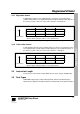
3.3 Memory Formats
ARM7TDMI views memory as a linear collection of bytes numbered upwards from
zero. Bytes 0 to 3 hold the first stored word, bytes 4 to 7 the second and so on.
ARM7TDMI can treat words in memory as being stored either in
Big Endian
or
Little
Endian
format.