
User guide


Signal Descriptions
ARM DUI 0224I Copyright © 2003-2010 ARM Limited. All rights reserved. A-5
A.3 UART interface
The PB926EJ-S provides four serial transceivers.
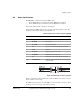
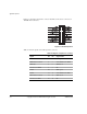
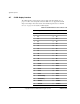
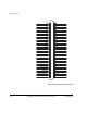
Figure A-4 shows the pin numbering for the 9-pin D-type male connector used on the
PB926EJ-S and Table A-4 shows the signal assignment for the connectors.
The pinout shown in Figure A-4 is configured as a Data Communications Equipment
(DCE) device.
Figure A-4 Serial connector
12
67 89
345
Table A-4 Serial plug signal assignment
Pin
UART0 J10A
(top)
UART1 J10B
(bottom)
UART2 J11A
(top)
UART3 J11B
(bottom)
1 SER0_DCD NC NC NC
2 SER0_RX SER1_RX SER2_RX SER3_RX
3 SER0_TX SER1_TX SER2_TX SER3_TX
4 SER0_DTR
SER1_DTR
a
a. The signals SER1_DTR, SER2_DTR, and SER3_DTR are connected to the
corresponding SER1_DSR, SER2_DSR, and SER3_DSR signals. These signals cannot
be set or read under program control.
SER2_DTR
a
SER3_DTR
a
5 SER0_GND SER1_GND SER2_GND SER3_GND
6 SER0_DSR SER1_DSR SER2_DSR SER3_DSR
7 SER0_RTS SER1_RTS SER2_RTS SER3_RTS
8 SER0_CTS SER1_CTS SER2_CTS SER3_CTS
9 SER0_RI NC NC NC