
User guide


PCI Backplane and Enclosure
D-2 Copyright © 2003-2010 ARM Limited. All rights reserved. ARM DUI 0224I
D.1 Connecting the PB926EJ-S to the PCI enclosure
This section describes how to configure the PCI backplane and connect the PB926EJ-S
to the PCI enclosure.
To use the PB926EJ-S with the PCI backplane and enclosure:
1. Configure the PB926EJ-S as described in Setting up the RealView Platform on
page 2-2.
Caution
Do not connect power to the PB926EJ-S yet.
2. Connect Multi-ICE to the board, or use the USB debug port. See Connecting
JTAG debugging equipment on page 2-8.
Note
The JTAG connection on the PB926EJ-S does not connect to the PCI backplane.
Use the PB926EJ-S JTAG for debugging applications.
There is also a JTAG socket on the PCI backplane. Only use this connector if you
are reprogramming the PAL on the PCI backplane.
3. Set the configuration switches on the PCI backplane. See Setting the backplane
configuration switches on page D-4.
4. If you are using an external display:
• For VGA displays, connect the cable from the display to the VGA
connector on the PB926EJ-S.
Note
If you are using a VGA card in the PCI bus, connect the VGA display to the
VGA connector on the PCI card. You must provide the interface code for
the PCI display card.
• For CLCD displays, connect the CLCD expansion board cable to the
PB926EJ-S and if necessary, connect the display interface cable from the
expansion board to the CLCD display. See Appendix C CLCD Display and
Adaptor Board.
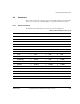
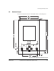
5. Slide the PB926EJ-S into the PCI connector on the side of the enclosure.
Figure D-1 on page D-3 illustrates an PB926EJ-S mounted in the PCI backplane
in the supplied enclosure.
6. Apply power to the PCI enclosure.