
User's Manual


Programmer’s Reference
4-2
© Copyright ARM Limited 1999. All rights reserved.
ARM DUI 0125A
4.1 Memory organization
This section describes the memory map. For a standalone core module, the memory
map is limited to local SSRAM, SDRAM, and core module registers. For the full
memory map of an Integrator development system, which includes a motherboard, you
should refer to the user guide for the motherboard.
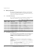
4.1.1 Core module memory map
The core module has a fixed memory map which maintains compatibility with other
ARM modules and Integrator systems. Table 4-1 shows the memory map.
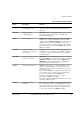
4.1.2 Boot ROM and SSRAM accesses
The boot ROM on the motherboard and the SSRAM on the core module share the same
location within the Integrator memory map. Accesses to either the boot ROM or
SSRAM are controlled by the REMAP bit and the motherboard detect signal
(nMBDET) from the motherboard, as shown in Table 4-1 on page 4-2.
Remap
The REMAP bit only has effect if the core module is attached to a motherboard
(nMBDET=0). It is controlled by bit 2 of the CM_CTRL register at 0x1000000C and
functions as follows:
REMAP=0 As it is after a reset. The Boot ROM on the motherboard appears in the
address range 0x0 to 0x3FFFF.
REMAP=1 The SSRAM appears in the 0x0 to 0x3FFFF address range.
Table 4-1 ARM Integrator/CM940T memory map
nMBDET REMAP Address range Region size Description
0 0 0x00000000 to 0x0003FFFF 256KB Boot ROM (on motherboard)
0 1 0x00000000 to 0x0003FFFF 256KB SSRAM
1 X 0x00000000 to 0x0003FFFF 256KB SSRAM
X X 0x00040000 to 0x0FFFFFFF 256MB Local SDRAM
X X 0x10000000 to 0x10FFFFFF 16MB Core module registers
0 X 0x11000000 to 0xFFFFFFFF 4GB to 272MB System bus address space
1 X 0x11000000 to 0xFFFFFFFF 4GB to 272MB Abort