
User guide

Trace Port Interface Unit
ARM DDI 0337I Copyright © 2005-2008, 2010 ARM Limited. All rights reserved. 11-12
ID072410 Non-Confidential
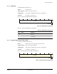
Table 11-10 shows the TPIU_ITCTRL bit assignments.
11.3.10 TPIU_DEVID
The TPIU_DEVID characteristics are:
Purpose Indicates the functions provided by the TPIU for use in topology
detection.
Usage constraints There are no usage constraints.
Configurations This register is available in all processor configurations.
Attributes See Table 11-1 on page 11-5.
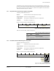
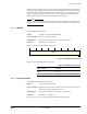
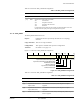
Figure 11-11 shows the TPIU_DEVID bit assignments.
Figure 11-11 TPIU_DEVID bit assignments
Table 11-11 shows the TPIU_DEVID bit assignments.
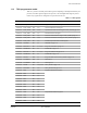
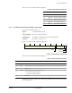
Table 11-10 TPIU_ITCTRL bit assignments
Bits Name Function
[31:2] - Reserved.
[1:0] Mode Specifies the current mode for the TPIU:
0b00
normal mode
0b01
integration test mode
0b10
integration data test mode
0b11
Reserved.
In integration data test mode, the trace output is disabled, and data can be read
directly from each input port using the integration data registers.
Reserved
31 12 11 10 9 8 6 5 0
Asynchronous Serial Wire Output (NRZ)
Asynchronous Serial Wire Output (Manchester)
Parallel trace port mode
Minimum buffer size
Asynchronous TRACECLKIN
4
Number of trace inputs
Table 11-11 TPIU_DEVID bit assignments
Bits Name Function
[31:12] - Reserved
[11] Asynchronous Serial Wire
Output (NRZ)
This bit Reads-As-One (RAO), indicating that the output is
supported.
[10] Asynchronous Serial Wire
Output (Manchester)
This bit Reads-As-One (RAO), indicating that the output is
supported.
[9] Parallel trace port mode This bit Reads-As-Zero (RAZ), indicating that parallel trace port
mode is supported.