
User guide

Functional Description
ARM DDI 0337I Copyright © 2005-2008, 2010 ARM Limited. All rights reserved. 2-2
ID072410 Non-Confidential
2.1 About the functions
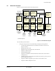
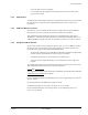
Figure 2-1 shows the structure of the Cortex-M3 processor.
Figure 2-1 Cortex-M3 block diagram
The Cortex-M3 processor features:
• A low gate count processor core, with low latency interrupt processing that has:
— A subset of the Thumb instruction set, defined in the ARMv7-M Architecture
Reference Manual.
— Banked Stack Pointer (SP).
— Hardware integer divide instructions,
SDIV
and
UDIV
.
— Handler and Thread modes.
— Thumb and Debug states.
— Support for interruptible-continued instructions
LDM
,
STM
,
PUSH
, and
POP
for low
interrupt latency.
— Automatic processor state saving and restoration for low latency Interrupt Service
Routine (ISR) entry and exit.
— Support for ARMv6 big-endian byte-invariant or little-endian accesses.
— Support for ARMv6 unaligned accesses.
†
†
Nested
Vectored
Interrupt
Controller
(NVIC)
Bus Matrix
Cortex-M3 processor
Trace Port
Interface
† CoreSight
ROM table
Serial-Wire or
JTAG Debug
Interface
ICode
AHB-Lite
instruction
interface
DCode
AHB-Lite
data
interface
System
AHB-Lite
system
interface
PPB APB
debug system
interface
Interrupts and
power control
Wake-up
Interrupt
Controller
(WIC)
Serial-Wire
or JTAG
Debug Port
(SW-DP or
SWJ-DP)
†
Embedded
Trace
Macrocell
(ETM)
†
†
Flash Patch
Breakpoint
(FPB)
†
Memory
Protection
Unit (MPU)
†
Data
Watchpoint
and Trace
(DWT)
†
AHB
Access Port
(AHB-AP)
†
Instrumentation
Trace Macrocell
(ITM)
Trace Port
Interface Unit
(TPIU)
Cortex-M3
processor core
† Optional component