
User guide

Programmers Model
ARM DDI 0337I Copyright © 2005-2008, 2010 ARM Limited. All rights reserved. 3-16
ID072410 Non-Confidential
3.7 Bit-banding
Bit-banding maps a complete word of memory onto a single bit in the bit-band region. For
example, writing to one of the alias words sets or clears the corresponding bit in the bit-band
region. This enables every individual bit in the bit-banding region to be directly accessible from
a word-aligned address using a single
LDR
instruction. It also enables individual bits to be toggled
without performing a read-modify-write sequence of instructions.
The processor memory map includes two bit-band regions. These occupy the lowest 1MB of the
SRAM and Peripheral memory regions respectively. These bit-band regions map each word in
an alias region of memory to a bit in a bit-band region of memory.
The System bus interface contains logic that controls bit-band accesses as follows:
• It remaps bit-band alias addresses to the bit-band region.
• For reads, it extracts the requested bit from the read byte, and returns this in the Least
Significant Bit (LSB) of the read data returned to the core.
• For writes, it converts the write to an atomic read-modify-write operation.
• The processor does not stall during bit-band operations unless it attempts to access the
System bus while the bit-band operation is being carried out.
The memory map has two 32-MB alias regions that map to two 1-MB bit-band regions:
• Accesses to the 32-MB SRAM alias region map to the 1-MB SRAM bit-band region.
• Accesses to the 32-MB peripheral alias region map to the 1-MB peripheral bit-band
region.
A mapping formula shows how to reference each word in the alias region to a corresponding bit,
or target bit, in the bit-band region. The mapping formula is:
bit_word_offset = (byte_offset x 32) + (bit_number
×
4)
bit_word_addr = bit_band_base + bit_word_offset
where:
•
bit_word_offset
is the position of the target bit in the bit-band memory region.
•
bit_word_addr
is the address of the word in the alias memory region that maps to the
targeted bit.
•
bit_band_base
is the starting address of the alias region.
•
byte_offset
is the number of the byte in the bit-band region that contains the targeted bit.
•
bit_number
is the bit position, 0 to 7, of the targeted bit.
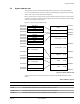
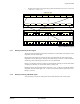
Figure 3-2 on page 3-17 shows examples of bit-band mapping between the SRAM bit-band
alias region and the SRAM bit-band region:
• The alias word at
0x23FFFFE0
maps to bit [0] of the bit-band byte at
0x200FFFFF
:
0x23FFFFE0
=
0x22000000
+ (
0xFFFFF
*
32
) +
0
*
4
.
• The alias word at
0x23FFFFFC
maps to bit [7] of the bit-band byte at
0x200FFFFF
:
0x23FFFFFC
=
0x22000000
+ (
0xFFFFF
*
32
) +
7
*
4
.
• The alias word at
0x22000000
maps to bit [0] of the bit-band byte at
0x20000000
:
0x22000000
=
0x22000000
+ (
0
*
32
) +
0
*
4
.