
User guide

Debug
ARM DDI 0337I Copyright © 2005-2008, 2010 ARM Limited. All rights reserved. 7-4
ID072410 Non-Confidential
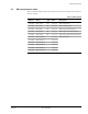
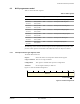
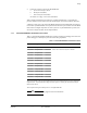
Table 7-2 shows the CoreSight components that the Cortex-M3 ROM table points to. The values
depend on the implemented debug configuration.
The ROM table entries point to the debug components of the processor. The offset for each entry
is the offset of that component from the ROM table base address,
0xE00FF000
.
See the ARMv7-M Architectural Reference Manual and the ARM CoreSight Components
Technical Reference Manual for more information about the ROM table ID and component
registers, and their addresses and access types.
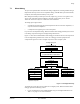
7.1.2 System Control Space
If debug is implemented, the processor provides debug through registers in the SCS. See:
• Debug register summary on page 7-5
• System address map on page 3-11.
Table 7-2 Cortex-M3 ROM table components
Address Component Value Description
0xE00FF000
SCS
0xFFF0F003
See System Control Space
0xE00FF004
DWT
0xFFF02003
a
a. Reads as
0xFFF02002
if no watchpoints are implemented.
See Table 8-1 on page 8-4
0xE00FF008
FPB
0xFFF03003
b
b. Reads as
0xFFF03002
if no breakpoints are implemented.
See Table 7-7 on page 7-10
0xE00FF00C
ITM
0xFFF01003
c
c. Reads as
0xFFF01002
if no ITM is implemented.
See Table 9-1 on page 9-4
0xE00FF010
TPIU
0xFFF41003
d
d. Reads as
0xFFF41002
if no TPIU is implemented.
See Table 11-1 on page 11-5.
0xE00FF014
ETM
0xFFF42003
e
e. Reads as
0xFFF42002
if no ETM is implemented.
See Chapter 10 Embedded Trace Macrocell.
0xE00FF018
End marker
0x00000000
See DAP accessible ROM table in the ARMv7-M
Architectural Reference Manual.
0xE00FFFCC
SYSTEM ACCESS
0x00000001