
User guide


Embedded Trace Macrocell
ARM DDI 0337I Copyright © 2005-2008, 2010 ARM Limited. All rights reserved. 10-3
ID072410 Non-Confidential
10.2 ETM functional description
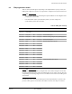
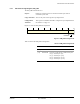
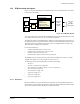
Figure 10-1 shows a block diagram of the ETM, and shows how the ETM interfaces to the Trace
Port Interface Unit (TPIU).
Figure 10-1 ETM block diagram
The Cortex-M3 system can perform low-bandwidth data tracing using the Data Watchpoint and
Trace (DWT) and Instruction Trace Macrocell (ITM) components.
The ETM trace output is compatible with the AMBA Trace Bus (ATB) protocol, irrespective of
the configuration of the trace port size and trace port mode within the ETM programmers model.
The TPIU exports trace information from the processor. An implementation can replace the
TPIU with other CoreSight trace components.
For more information see:
• Chapter 8 Data Watchpoint and Trace Unit
• Chapter 9 Instrumentation Trace Macrocell Unit
• Chapter 11 Trace Port Interface Unit
• Embedded Trace Macrocell Architecture Specification.
The ETM provides a trace ID register for systems that use multiple trace sources. You must
configure this register even if only a single trace source is in use.
The following sections provide information on features of the ETM:
• Resources
• Periodic synchronization on page 10-6
• Data and instruction address compare resources on page 10-6
• External inputs on page 10-6
• Start/stop block on page 10-6
• Triggering on page 10-7
• Interfaces on page 10-7
• Operation on page 10-8.
10.2.1 Resources
Because the ETM does not generate data trace information, the lower bandwidth reduces the
requirement for complex triggering capabilities. This means that the ETM only includes a small
sub-set of the possible resources allowed by the ETM architecture.
Cortex-M3
processor
DWT
ITM
ATB
ETM-M3
ATB
Cortex-M3
TPIU or
Coresight
system
CTI
Trace port
and
SerialWire
trace outputs
Trace Generation
Trace Control:
Counter
Start/Stop block
Trigger generation
Programming interface