99 Washington Street Melrose, MA 02176 Phone 781-665-1400 Toll Free 1-800-517-8431 Visit us at www.TestEquipmentDepot.com GFL3000 Gro u n d Fa u lt Lo c a to r Op e ra tin g In s tru c tio n s WARNING – Re a d a n d u n d e rs ta n d th e in s tru c tio n s b e fo re op e ra tin g th is u n it. Fa ilu re to d o s o c o u ld le a d to in ju ry o r d e a th .
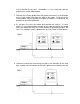
The Armada Technologies GFL3000 Ground Fault Locator is designed to find wire or cable damage that results in an electrical path to ground. The GFL3000 works on the principle of earth gradient theory and is sometimes referred to as an earth gradient fault detector. The GFL3000 will pinpoint the exact location of a grounded cable fault. The GFL3000 is NOT a cable path locator. You will likely need a separate cable locator to locate the path of the entire cable.
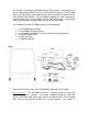
determined by the relative resistance of the fault and subsequent path to the ground stake versus the other available paths for the current. The receiver/A-frame is then inserted into the ground along the path of the wire. As the current flows down the wire, it travels out through the ground fault and then back to the ground stake. Some of this current, however, travels through the A-frame receiver. The needle at the top of the A-Frame will give a directional kick either left or right.
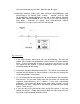
Op e ra tio n 1. Disconnect cable to be tested at both ends. Be sure you are disconnected from power, components or anything else that will transmit electrical current. This isolates the cable and forces the current generated by the GFL3000 to exit the cable at the fault. 2. Assemble the A-Frame receiver by placing the small electronic receiver module on top of the receiver frame and secure it with the 2 thumb screws attached to the A-Frame. 3.
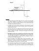
in the direction of the fault. Remember, it is the initial kick you are watching for, not the rebound kick. 7. Remove the A-Frame probes from the ground and move it in the direction of the initial needle kick along the path of the cable. Re-insert the AFrame probes into the ground and repeat the process of observing the direction of the initial needle kick. 8. As you pass the fault, the needle kick direction will reverse.
fault, the needle will cease to kick. Mark the spot for repair. 10. BEFORE REP AIR, TURN OFF THE GFL3000 TRANS MITTER AND DIS CONNECT IT FROM THE CABLE. NEVER TOUCH THE TRANS MITTER, TRANS MITTER LEADS OR CABLE BEING TES TED WHILE THE TRANS MITTER IS ON. DO NOT US E THE GFL3000 IN THE RAIN. FAILURE TO READ AND UNDERS TAND THES E WARNINGS COULD LEAD TO INJ URY OR DEATH. Tip s a n d No te s 1. If the cable contains many faults, this can be confusing.
5. If you cannot insert the A-Frame probes into the ground due to concrete, asphalt, try using wet sponges. This will increase the conductivity of the frame. You can also extend the frame by wrapping a wire around one foot of the A-Frame and connecting the other end of the wire to a screwdriver. This in effect increases the size of the A-Frame and allows the blocking feature to be straddled.