
Installation Guide

Installation:
15
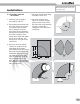
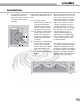
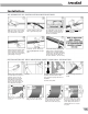
6. The last piece of insulation
needed will insulate the
bonnet area. This is shown
in Figure 6 and is made as
shown in
Figure 6A. The measurements for
Figure 6A are determined as fol-
lows:
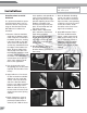
C—The overall length is
determined by wrapping a
strip of Armaflex Sheet
around the bonnet flange
(do not stretch) and mark-
ing where the ends meet.
L1—This distance is obtained by
measuring from the outer
surface of the Armaflex
donut to the approximate
middle of the valve body
insulation.
L2—This distance is obtained by
measuring from the outer
surface of the Armaflex
donut to the closest surface
of the valve body insula-
tion.
Y—is the difference between L1
and L2.
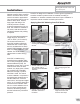
The bonnet insulation of Armaflex
Sheet is cut to the size of C x L1.
This is then marked to show L2
and marked in quarters as shown
in Figure 6A. Next the scalloped
edge of the insulation is deter-
mined by swinging an arc from
each point marked + in Figure
6A. The radius of the arc is equal
to Y. These arcs are connected
with straight lines to give a
smooth scalloped edge (see
Figure 6B). The scalloped edge
of the insulation must be under-
cut (beveled) to correctly meet
the body insulation.
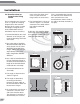
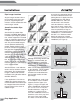
The bonnet insulation may now
be installed using 520 or 520 BLV
Adhesive to bond the two ends,
to adhere the bonnet insulation to
the body insulation and to adhere
the bonnet insulation around the
Armaflex donut. This should com-
plete the flange valve fitting.
▲
▲
▲
▲
▲
▲
▲
▲
▲
▲
▲
▲
▲
▲
▲
▲
▲
▲
▲
▲
C
Y
Y
1/4 C
1/4 C
1/4 C
L
2
L
1
1/4 C
Y
6 B
6A
6
Bonnet area
▲
L
1
▲
▲
▲
L
2
▲