PVS-14/6015 Night Vision Monocular Operation and Maintenance Manual Shop for Armasight products online at: Important Export Restrictions! Commodities, products, technologies and services of this manual are controlled by the U.S. Department of State Office of Defense Trade Controls, in accordance with International Traffic in Arms (ITAR), Title 22, Code of Federal Regulations Part 120-130 and/or by the Export Administration Regulations (EAR) of U.S. Department of Commerce.
SAFETY SUMMARY Before operating this product, carefully read and study this Operation and Maintenance Manual. The PVS-14/6015 is a precision electro-optical instrument, and requires careful handling. To avoid damage to the equipment or physical harm to the user when operating the PVS-14/6015, follow all WARNINGS, CAUTIONS and NOTES. Below you will find definitions of the following alerts that appear throughout this Manual: WARNING — Identifies a clear danger to the person operating the equipment.
CAUTION: • The PVS-14/6015 is a precision optical instrument and must be handled carefully at all times to prevent damage. • To prevent damage, be especially careful when leaving the helmet mount in the flipped up position or removing the helmet mount from the helmet. • Do not scratch the external lens surfaces or touch them with your fingers. • Do not wipe the demisting shield with lens paper while it is damp, or using wet lens paper, as this can damage the coating.
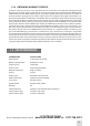
LIST OF CONTENTS TITLE PAGE Safety Summary List of Contents List of Figures How to Use This Manual 1. INTRODUCTION 1.1 General Information 1.1.1 Type of Manual 1.1.2 Model Number and Equipment Name 1.1.3 Purpose of Equipment 1.1.4 Reporting Equipment Improvement Recommendations 1.2 Warranty Information and Registration 1.2.1 Warranty Information 1.2.2 Limitation of Liability 1.2.3 Product Warranty Registration 1.2.4 Obtaining Warranty Service 1.3 Cross References 1.4 List of Abbreviations 1.5 Glossary 2.
3.3.10 Installation of the Weapon Mount 3.3.11 Installation of the Compass Caution 3.3.12 Installation of the 3x Magnifier 3.3.13 Mounting MUNVM to a Weapon with a Quick-Release Picatinny Mount Adapter 3.3.14 Mounting a MUNVM to a Weapon with the AIM Advanced Integrated Mount 3.4 Operating Procedures 3.4.1 Hand-Held Operation 3.4.2 Head-Mounted Operation 3.4.3 Helmet-Mounted Operation 3.4.4 Weapon-Mounted Operation 3.4.5 IR Source Operations 3.4.6 Operation with a Compass 3.4.
3-1. Monocular Controls and Indicators 3-2. TS-4348/ UV Test Set Pattern 3-3. Shading 3-4. Edge Glow 3-5. Bright Spots and Emission Points 3-6. Fixed-Pattern Noise 3-7. Chicken Wire 3-8. Battery, Eyecup and Eyeguard Installation 3-9. MUNVM Headmount Adjustments 3-10. Headmount/Helmet Mount Adapter Installation 3-11. Installation of Helmet Mount 3-12. Helmet Mount 3-13. Reassembly of Helmet Mount 3-14. Weapon Mount Usage 3-15. Locating the Magnet 3-16. Compass Installation 3-17.
1 INTRODUCTION 1.1 GENERAL INFORMATION 1.1.1 TYPE OF MANUAL Operation and Maintenance. 1.1.2 Model Number and Equipment Name PVS-14 Multi-Use Night Vision Monocular. 6015 Multi-Use Night Vision Monocular. 1.1.3 PURPOSE of Equipment To provide the operator with the ability to observe at night under moonlight and starlight conditions.
1.2 warranty INFORMATION and Registration 1.2.1 WARRANTY INFORMATION This product is guaranteed to be free from manufacturing defects in material and workmanship under normal use for a period of two (2) years from the date of purchase.
1.2.4 Obtaining Warranty Service To obtain warranty service on your unit, the End-user (Customer) must notify the Armasight service department via email. Send any requests to service@armasight.com to receive a Return Merchandise Authorization number (RMA). When returning any device, please take in the product to your retailer, or send the product, postage paid and with a copy of your sales receipt, to Armasight Corporation’s service center at the address listed above.
1.
1.5 GLOSSARY BLACK SPOTS. Cosmetic blemishes in the image intensifier of the MUNVM, or dirt or debris between the lenses. BRIGHT SPOTS. Defects that can appear in the image area of the MUNVM. This condition is caused by a flaw in the film on the microchannel plate. A bright spot is a small, non-uniform, bright area that may flicker or appear constant. Bright spots are cosmetic blemishes that are signal-induced, and usually disappear when all light is blocked out. BROWPADS.
2 DESCRIPTION AND DATA 2.1 EQUIPMENT description 2.2.1. EQUIPMENT CHARACTERISTICS, CAPABILITIES, AND FEATURES The PVS-14/6015 is a hand-held, head-mounted, helmet mounted, or weapon-mounted night vision system that enables walking, weapon firing, short-range surveillance, map reading, vehicle maintenance, and administration of first aid in both moonlight and starlight conditions.
HEAD/HELMET MOUNT ADAPTER WEAPON MOUNT TETHERING CORD HEADMOUNT THIN BROWPAD HELMET MOUNT BATTERY CARTRIDGE MEDIUM AND THICK BROWPADS CARRYING CASE OPERATOR’S MANUAL LENS PAPER NECK CORD DEMIST SHIELD SACRIFICIAL WINDOW BATTERy EYEGUARD OBJECTIVE LENS CAP CARRYING CASE STRAP MONOCULAR Figure 2-1. Components of NVMPS COMPASS 3X MAGNIFIER (ADDITIONAL ITEM) Figure 2-2. 3X Magnifier and Compass for PVS-14/6015 Shop for Armasight products online at: www.SCOUTBASECAMP .ca 1.877.766.
(see Figure 2-1. for details) SHIPPING AND STORAGE CASE Figure 2-3. Shipping and storage cases for PVS-14/6015 EYEPIECE LENS OBJECTIVE LENS POWER SWITCH BATTERY CAp GAIN CONTROL Figure 2-4. Multi-Use Night Vision Monocular Bracket AIM AIM PVS14 Kit (ANKI000046) Double Lever-Lock Quick Release Picatinny Mount Adapter #26 (ANAM000004) Bracket PVS14 #62 (ANKI000046) Figure 2-5. Optional Equipment Shop for Armasight products online at: 14 www.SCOUTBASECAMP .ca 1.877.766.
c. Helmet Mount The helmet mount (Figure 2-1) secures the monocular to the Personal Armor System Ground Troops (PASGT) helmet, allowing freehand support for use with a weapon, protective mask and/ or other purposes in which freehand operation is required. The new helmet mount is made of a ruggedized metal, unlike the older version, which is made of plastic. d.
Table 2-3. MECHANICAL DATA ITEM CHARACTERISTICS Shipping and Storage Case Size: Approx. 356 x 241 x 203 mm (14” x 9.5” x 8”) Weight: 1.09kg (2.4 lbs.) Carrying Case Size: Approx. 352 x 240 x 200 mm (14” x 9.5” x 8”) Monocular (see Note) Weight: 0.39kg (14 ounces) NOTE: The weight of the monocular does not include accessories. Table 2-4. OPTICAL DATA ITEM DATA Magnification 1.
MICROCHANNEL PLATE FIBER-OPTIC INVERTER PHOTOCATHODE OBJECTIVE LENS PHOSPHOR SCREEN IMAGE INTENSIFIER POWER SUPPLY EYEPIECE LENS EYE Figure 2-6. Optical Function Diagram 2.3.3. ELECTRONIC CIRCUIT FUNCTION The electronic circuit regulates the direct current voltage from the battery to the image intensifier and IR source as required. It also monitors the output voltage of the battery and turns on a low-battery indicator when the available battery voltage is 1.9 – 2.1 Vdc. a.
3 OPERATING INSTRUCTIONS 3.1 Description and Use of Operator’s Controls and Indicators NOTE: The MUNVM is a precision electro-optical instrument, and must be handled carefully. If the equipment fails to operate, refer to the Troubleshooting Procedures in Chapter 4. 3.1.1. OPERATOR CONTROLS AND INDICATORS The MUNVM is designed to adjust for different users and corrects for most differences in eyesight. The controls and indicators for the MUNVM are shown in Figure 3-1, and are described in Table 3-1.
NOTE: The gain control function is not available with the 6015 model. NOTE: Indicators showing that the battery is low and that the IR is active are both visible in the eyepiece lens. Table 3-1. MONOCULAR CONTROLS AND INDICATORS CONTROLS AND INDICATORS FUNCTIONS Controls the monocular and IR source, ON or OFF. Power Switch RESET/ OFF Same as system OFF. Also resets monocular after high light cut-off. ON Monocular activated. IR/ PULL Turn the knob clockwise to momentarily activate the IR source.
3.2 Preventive Maintenance Checks and Services (PMCS) 3.2.1. PREVENTIVE MAINTENANCE CHECKS AND SERVICES a. General To verify that the MUNVM is mission-ready, perform the preventive maintenance procedures in accordance with Table 2.2 prior to each mission. Preventive maintenance procedures include inspection, cleaning, and performance of the checkout procedures. b. Warnings and Cautions Always observe the WARNINGS and CAUTIONS appearing in the table.
Table 3-1. Preventive maintenance procedures ITEM INTERVAL NO. CHECK/SERVICE PROCEDURE 1 Before Open carrying case and inventory the items. MONOCULAR 2 Before/ Optical After Surfaces 3 Before/ Battery Cap After Housing Inspect all lenses (objective, eyepiece, IR lens and high light cut-off window) for dirt, fingerprint residue, chips, or cracks. If necessary, clean and dry lenses with water and lens tissue. Inspect external surfaces for cracks or damage.
table 3-1. continued ITEM INTERVAL NO. 4 5 6 7 8 CHECK/SERVICE PROCEDURE Before/ Monocular After Inspect for cracks or damage. Scratches, cracks, chips and gouges are OK if operation is not affected. Before/ Eyepiece Lens Rotate diopter adjustment to make After sure the eyepiece lens moves freely and is not loose. Range is approximately ½ turn. Before/ Eyecup Inspect for dirt, dust, cracked or torn After eyecup. Inspect for bent, broken, or improperly fitting eyepiece lens.
table 3-1. continued ITEM INTERVAL NO. 12 CHECK/SERVICE Before/ Socket After 13 Before /After Eye Relief Adjustment 14 Before /After Straps 15 Before /After Socket 16 Before /After Fore-and-Aft Adjustment PROCEDURE Inspect for dirt, dust, or corrosion. Insert monocular latch into socket to verify secure attachment of monocular to headmount. If necessary, clean socket with water. Press the eye relief adjustment and check for free motion. Inspect for damage. NOT FULLY MISSION CAPABLE IF...
table 3-1. continued ITEM INTERVAL NO. 21 Before /After CHECK/SERVICE Compass 22 Before /After 3X Magnifier (Additional Authorized Item) 23 Before /After Case 24 Before /After Shoulder Strap PROCEDURE NOT FULLY MISSION CAPABLE IF... Inspect for dirt, dust, scratches, or Damaged; compass is not damage. If necessary, clean with water visible. and dry with lens tissue. Install compass and turn on monocular. When the illumination button is depressed, compass should be visible.
NOTE: • The resolution test must be performed in a darkened area. Your eyes must be dark-adapted to perform this test. Review the following test procedure before entering the dark area: - When viewing through the TS-4348/ UV Test Set on the “high light” level, expect cosmetic blemishes, such as chicken wire, black spots, and fixed-pattern noise, to stand out. This is acceptable. - Returns of the MUNVM for cosmetic defects must be based on an outdoor evaluation, not the TS-4348/ UV Test Set. b.
(9) To pass the test, the MUNVM must be able to resolve Group 3, Element 5, under high light conditions. If the monocular does not pass the test, please contact Customer Support, as you will need to return the device for repair. NOTE: When using the TS-4348/ UV Test Set, you are not viewing the entire image intensifier. Therefore, operational and cosmetic inspections must be done without the test set as specified in paragraph 3.2.3.
NOTE: Always verify that shading is not the result of improper eye-relief adjustment (refer to paragraph 3.4.2). (2) Edge Glow. Edge glow is a bright area (sometimes sparkling) in the outer portion of the viewing area (see Figure 3-4). To check for edge glow, block out all light by cupping a hand over the objective lens. If the image intensifier is displaying edge glow, the bright area will still appear. If edge glow occurs, you will need to return the MUNVM to the manufacturer. Edge Glow Figure 3-4.
(2) Emission Points. A steady or fluctuating pinpoint of bright light in image area that does not go away when all light is blocked from the objective lens of the monocular (Figure 3-5). The position of an emission point within the image area does not move. Not all emission points make the MUNVM returnable. Verify that any emission points are not simply a point light source in the distance of the scene you are viewing.
3.3 Assembly and Preparation for Use 3.3.1. UNPACKING The following steps must be taken prior to each mission in which the MUNVM is used. CAUTION: Relieve air pressure from inside the shipping and storage case by compressing opposite sides of the case before releasing the latches. (1) Release the latch securing the top of the shipping and storage case and open it. (2) Verify that all items were shipped (see Figure 2-1). (3) Open the carrying case (Figure 2-3), remove MUNVM, and inventory the items.
SACRIFICIAL WINDOW EYECUP DEMIST SHIELD BATTERY CAp EYEGUARD battery Figure 3-8. Battery, Eyecup and Eyeguard Installation 3.3.3. INSTALLATION OF the EYECUP OR EYEGUARD Perform the following procedure to install eyecup or eyeguard onto the monocular. Refer to Figure 3-8. (1) Carefully press the eyecup or eyeguard over the end of the eyepiece lens. (2) Rotate the eyecup or eyeguard into proper viewing position. Adjust for the best fit.
(1) If the objective lens cap is in place, remove it. (2) Carefully push the sacrificial window onto the objective lens until it stops. Turn the sacrificial window clockwise until it snaps into place. 3.3.6. INSTALLATION AND ADJUSTMENT OF the HEADMOUNT Perform the following to install the headmount. NOTE: Do not put the headmount on with the monocular attached. (1) Before putting the headmount on, loosen the four ends of the chinstrap (approximately two inches from the sliding bar buckles; see Figure 3-9).
NOTE: After installing the monocular, minor strap adjustments may be necessary to achieve maximum comfort. (8) Install the headmount/ helmet mount adapter (refer to paragraph 3.3.7). (9) Refer to paragraph 3.4.2 for operating procedures. 3.3.7. INSTALLATION OF the HEADMOUNT/ HELMET MOUNT ADAPTER To install the headmount/ helmet mount adapter (Figure 2-1) into the monocular, align the thumbscrew to the hole and tighten it as shown in Figure 3-10.
(11) Insert the top edge of the mount under the keeper on the helmet mount bracket and rotate it downward until the latch engages (see Figure 3-13). To release the mount from the helmet bracket, press the release and pull it forward and down. HELMET MOUNT BRACKET KEEPER CATCH BUCKLE LEVER STRAP REAR SNAP REAR MOUNTING HOLE NAPE STRAP REAR BRACKET Figure 3-11. Installation of Helmet Mount TOP EDGE OF MOUNT HELMET MOUNT BRACKET MOUNT STRAP KEEPER RELEASE MOUNT IS ROTATED 90° FOR CLARITY Figure 3-12.
WARNING: When installing the headmount over the protective mask, be careful that you do not break the mask’s seal around your face. (2) Install the headmount per the instructions in paragraph 3.3.6. NOTE: It may be necessary to remove the browpad (Figure 3-9) when wearing the headmount over a protective mask. 3.3.10. INSTALLATION OF the WEAPON MOUNT Perform the following to install the weapon mount. weapon MOUNT alignment boss (hidden) thumbscrew clamping knob Figure 3-14.
(4) Check the position of the monocular by holding the weapon in your normal firing position. Adjust the fore/aft position of the monocular as necessary by loosening the clamping knob and repositioning the weapon mount on the weapon’s mounting rail. 3.3.11. INSTALLATION OF the COMPASS CAUTION: • Use of the compass with the plastic headmount or the plastic helmet mount will result in inaccurate compass readings. The magnet cannot be removed from these mounts.
(5) Ensure that the compass fits tightly to the objective lens. (6) Refer to paragraph 3.4.6 for compass operation. 3.3.12. INSTALLATION OF the 3X MAGNIFIER The 3X magnifier can be threaded directly into the objective lens. It can also be threaded into the focus ring adapter and slipped on over the end of the objective lens. Figures 3-17 and 3-18 illustrate these installation procedures. thread directly into objective lens as shown Figure 3-17.
C B D A Figure 3-19. MOUNTING OPTIONAL Bracket TO THE MUNVM A B C Figure 3-20. CLAMPING DEVICE ON THE MOUNT TOP Figure 3-21. QRM ASSEMBLED WITH MUNVM 3.3.14. MOUNTING A MUNVM TO A WEAPON WITH THE AIM ADVANCED INTEGRATED MOUNT The MUNVM is mounted to the AIM using the bracket from the AIM PVS14 Kit. Figure 3-22. AIM ASSEMBLED WITH MUNVM Shop for Armasight products online at: www.SCOUTBASECAMP .ca 1.877.766.
The clamping system of the AIM is the same as is seen on the QRM. To mount the MUNVM to a weapon with an AIM, see Part 3.3.13 of this Manual. This section describes mounting instructions and procedures for the QRM. MUNVM installed onto the AIM is shown in Figure 3-22. For more information on the use of an AIM, see the AIM Operation Manual. 3.4 Operating Procedures This section contains operating procedures for using the NVMPS as hand-held, head-mounted, helmetmounted or weapon-mounted monocular.
Release the latch when the monocular is fully engaged in the socket. (4) To set your eye relief, press down on the eye relief adjustment (Figure 3-19). Move the monocular back towards your non-dominant eye until the eyecup is comfortably sealed around the eye. (5) Turn the monocular ON. (6) Readjust the vertical adjustment (Figure 3-9) of the headmount until the monocular is properly aligned with your eye. headmount socket latch eye relief adjustment Figure 3-23.
CAUTION: • To prevent damage, do not use excessive force when changing the up/ down position of the MUNVM. • Do not drop or throw the helmet with the helmet mount attached to it. • If the monocular is flipped up, do not flick the monocular down by shaking the helmet. This places significant stress on the helmet mount. • All Other Services – Return the helmet and the helmet mount to unit maintenance to have the bracket directly mounted via the helmet screws.
NOTE: The sharpest image will be visible only when the objective lens and eyepiece lens are properly focused. (5) Rotate the diopter adjustment for the clearest view of the image intensifier screen. NOTE: Any readjustment for eye relief requires readjustment of the diopter. (6) Adjust the eye relief distance by depressing the side buttons (Figure 3-24) (or, if using a metal mount, the side lever) and sliding the monocular back and forth until you obtain a full view of the image.
3.4.5. IR SOURCE OPERATIONS WARNING: The IR source is invisible to the naked eye, and is intended for use in extremely dark conditions. However, this light can be detected by other night vision devices. NOTE: The IR source is intended for viewing at close distances (up to 3 meters) when additional illumination is needed. (1) Pull the power switch knob out and rotate it clockwise to the IR position. With the monocular held to the eye, verify that a red light appears in the eyepiece.
Figure 3-25. View Through Installed Compass (3) To view the compass through the monocular, grip the compass with your index finger on top and your thumb on the illumination button on the bottom. Press the button slowly with your thumb until the proper brightness is obtained. The image should appear as shown in Figure 3-25. (4) The compass readings should change when you move your head from side to side. Rotate or tap the compass slightly to ensure that the compass is operating correctly.
3.4.9. PREPARATION FOR STORAGE (1) Perform the following to shut down the monocular. (a) Turn the monocular OFF. (b) Remove the monocular from the headmount, helmet mount or weapon, and remove the weapon mount from the monocular. WARNING: Do not carry batteries in pockets containing metal objects such as coins, keys, etc. Metal objects can cause the batteries to short circuit and become very hot when inserted into the device. (2) Packaging After Use. (a) Remove the battery cap and battery.
3.5.2. OPERATION IN RAINY OR HUMID CONDITIONS CAUTION: Operation in rainy or humid conditions can cause corrosion and deterioration of the MUNVM, unless the below precautions are observed. (1) Install the demist shield (paragraph 3.3.4). (2) Keep the carrying case and the shipping and storage case closed unless removing or replacing items. (3) Dry the monocular, mounts, and accessories after exposure to rain or high humidity, and always before storage. This will prevent mildew from forming in the case.
4 MAINTENANCE procedures AND TROUBLESHOOTING 4.1 Lubrication Instructions No lubrication is required. 4.2 Troubleshooting Procedures 4.2.1. TROUBLESHOOTING Table 4.1 lists common malfunctions that may occur with the equipment. Perform the tests, inspections and corrective actions in the order they appear in the table.
table 4-1. continued MALFUNCTION 5. Light visible around eyecup. TEST OR INSPECTION Check eye relief distance. CORRECTIVE ACTION Check eyecup for resiliency. Readjust for proper eye relief distance. 6. Diopter adjustment cannot be made. Check to see if the diopter adjustment is bent or broken. If damaged, please contact Customer Support. 7. Battery cap difficult to open. Visually inspect for the presence of an o-ring. If o-ring is missing, please contact Customer Support.
4.3.2. HEADMOUNT MAINTENANCE a. Browpad Replacement Replace the browpad when cracked, torn, or contaminated. Perform the following to remove and replace the browpad. (1) Firmly grasp the headmount and remove the old browpad. (2) Gently press on the new browpad. Gently smooth out any wrinkles in the new browpad. b. Neck Pad Reinstallation During operation of the MUNVM, it is possible for the neck pad to become separated from its position on the headband. Perform the following to reinstall the neck pad.
When putting on and adjusting the headmount, it is possible for the strap to slip out of the slide fastener. Perform the following to adjust the strap and sliding bar buckle. (1) Thread the strap from the inside of the buckle over the moveable sliding bar (see Figure 4-2.). Thread the strap back through the buckle; this time, thread it under the moveable sliding bar and over the serrated part of the buckle. (2) Pull the strap through the buckle and tighten.
Appendix A. COMPONENTS OF END ITEM (COEI) AND BASIC ISSUE ITEMS (BII) LISTS A1. SCOPE To help you inventory components and to promote safe and efficient operation of the equipment, this appendix lists COEI and BII for the PVS-14/ 6015. A2. GENERAL The COEI and BII information is divided into the following lists: Components of End Item (COEI). This list is for information purposes only, and is not a basis for requesting returns or replacements. These items are part of the PVS-14/ 6015.
4 5 8 3 2 1 7 6 10 11 13 9 14 12 15 16 17 18 19 20 Figure A-1.Components of End Item TABLE A-1. Components of End Item (1) ILLUS.
B. ADDITIONAL AUTHORIZATION LIST (AAL) B1. SCOPE This appendix lists additional items you are authorized to use to supplement the PVS-14/ 6015. B2. GENERAL This list identifies items that do not have to accompany the PVS-14/ 6015 and that do not have to be returned with it. These items are all authorized for your use by CTA, MTOE, TDA, or JTA. B3. EXPLANATION OF COLUMNS IN THE AAL Column (1), National Stock Number. Identifies the stock number of the item to be used for requisitioning purposes.
c. EXPENDABLE AND DURABLE ITEMS LIST C1. SCOPE This appendix lists expendable and durable items that you will need in order to operate and maintain the PVS-14/ 6015. This list is for information only and is not basis for requesting returns. C2. EXPLANATION OF COLUMNS IN THE EXPENDABLE/DURABLE ITEMS LIST Column (1) - Item Number. This number is assigned to the entry in the list and is referenced in the narrative instructions to identify the item. Column (2) - Level.
D. Product Warranty Registration Card In order to validate the warranty on your product, Armasight must receive a completed Product Warranty Registration Card for each unit, or the user must complete warranty registration on our website (www.armasight.com). Please complete the included form and immediately mail it to our Service Center: Armasight Inc.
ALPHABETICAL INDEX A Abbreviations, list of 10 Additional Authorization List 52 Adjustment (See specific adjustment) Ambient temperature limits 11 B Basic Issue Items List 50 Battery AA size 15 Alkaline 15 Installing 29 Life 29 Lithium 15 Low battery indicator 12, 19 Polarity Indicators 29 Voltage 15 Black spots 11, 28 Bright spots 11, 8 Browpads 11, 13, 31 C Capabilities 12 Characteristics 15 Checks, preventive maintenance 20 Chicken wire 11, 25 Cleaning the MUNVM 47 Compass Installation 35 Operation 42 Co
Armasight Inc. 815 Dubuque Avenue, South San Francisco, CA 94080, USA Phone: (888)959-2259 Fax: (888)959-2260 Intl Phone/Fax: (650)492-7755 info@armasight.com CAUTION: This product contains natural rubber latex which may cause allergic reactions! The FDA has noted an increase in the number of reported deaths that are associated with an apparent sensitivity to natural latex proteins.