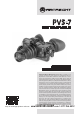
PVS-7 NIGHT VISION GOGGLES Operation and Maintenance Manual Shop for Armasight products online at: Important Export Restrictions! Commodities, products, technologies and services of this manual are controlled by the U.S. Department of State Office of Defense Trade Controls, in accordance with International Traffic in Arms (ITAR), Title 22, Code of Federal Regulations Part 120-130 and/or by the Export Administration Regulations (EAR) of U.S. Department of Commerce.
SAFETY SUMMARY Before operating this product, carefully read and study this Operation and Maintenance Manual. The PVS-7 is a precision electro-optical instrument, and requires careful handling. To avoid damage to the equipment or physical harm to the user when operating the PVS-7, follow all WARNINGS, CAUTIONS and NOTES. Below you will find definitions of the following alerts that appear throughout this Manual: WARNING — Identifies a clear danger to the person operating the equipment.
CAUTION: • The PVS-7 is a precision optical instrument. To prevent damage to the unit, it should always be handled carefully. • Do not scratch the external lens surfaces or touch them with your fingers. • To protect the image intensifier, keep the lens cap securely fitted over the objective lens when the device is not in use, or when it is being used in daylight conditions. • The IR illuminator produces light that is invisible to a naked eye, so that it can be used in conditions of extreme darkness.
LIST OF CONTENTS TITLE PAGE Safety Summary List of Contents How to Use This Manual 1. INTRODUCTION 1.1 General Information 1.1.1 Type of Manual 1.1.2 Model Number and Equipment Name 1.1.3 Purpose of Equipment 1.1.4 Reporting Equipment Improvement Recommendations 1.2 Warranty Information and Registration 1.2.1 Warranty Information 1.2.2 Limitation of Liability 1.2.3 Product Warranty Registration 1.2.4 Obtaining Warranty Service 1.3 Cross References 1.
4.3 Maintenance 4.3.1 General 4.3.2 Head Mount Maintenance 4.4 Service/Packing and Unpacking 4.4.1 Return Instructions 36 36 37 37 37 APPENDIX A. PVS-7 List of Spare Parts B.
LIST OF Tables TABLE TITLE PAGE 2-1 2-2 2-3 2-4 2-5 2-6 2-7 2-8 3-1 3-2 3-3 4-1 A-1 PVS-7 System Description PVS-7 Optional Equipment Operator Adjustment Limits Electrical Data Mechanical Data Optical Data Environmental Data Consumable Items Controls and Indicators Preventive Maintenance Checks and Services Estimated Battery Life Operator’s Troubleshooting PVS-7 List of Spare Parts 12 12 13 13 13 13 14 15 17 18 21 33 39 HOW TO USE THIS MANUAL USAGE You must familiarize yourself with the entire manual
1 INTRODUCTION 1.1 GENERAL INFORMATION 1.1.1 TYPE OF MANUAL Operation and Maintenance. 1.1.2 Model Number and Equipment Name PVS-7 Night Vision Goggles 1.1.3 PURPOSE of Equipment To provide the operator with the ability to observe scenes at night, under moonlight and starlight conditions. The PVS-7 can be used as a handheld, head-mounted or helmet-mounted device.
1.2 warranty INFORMATION and Registration 1.2.1 WARRANTY INFORMATION This product is guaranteed to be free from manufacturing defects in material and workmanship under normal use for a period of two (2) years from the date of purchase.
1.2.4 Obtaining Warranty Service To obtain warranty service on your unit, the End-user (Customer) must notify the Armasight service department via email. Send any requests to service@armasight.com to receive a Return Merchandise Authorization number (RMA). When returning any device, please take in the product to your retailer, or send the product, postage paid and with a copy of your sales receipt, to Armasight Corporation’s service center at the address listed above.
1.
2 DESCRIPTION AND DATA 2.1 System DESCRIPTION The PVS-7 is a hand-held, head-mounted or helmet-mounted night vision system that enables mobility, driving, weapon firing, short-range surveillance, map reading, vehicle maintenance and administering first aid during operation in both moonlight and starlight. Each unit allows for vertical adjustment (using the head straps), fore-and-aft adjustment, objective lens focus, eyepiece focus and eye relief distance adjustment.
5 6 8 7 9 1 13 4 2 3* 12 11 10 Figure 2-1. PVS-7 Components Table 2-1. PVS-7 System Description Item 1 Description Item PVS-7 Assembly 8 Description Neck Cord 2 AA Alkaline Batteries 9 Shoulder Strap Assembly 3* Image intensifier Tube 10 Demist Shield Assembly 4 Large Brow Pad Head mount Assembly 11 Sacrificial Window 5 Large Brow Pad 12 Operator’s Manual 6 Medium Brow Pad 13 Carrying Case 7 Thin Brow Pad 14 Lens Paper (Not Shown) * Equipment with variants.
2.2 Specifications The following tables provide information pertaining to the operational, electrical, mechanical, optical and environmental characteristics for the goggles. Table 2-3. Operator Adjustment Limits Item LIMITS Interpupillary Distance 55 to 71mm Diopter Focus +2 to -6 diopters Objective Focus 25cm to infinity Table 2-4. Electrical Data ITEM DATA Power Source Battery (3 VDC max.) Battery Requirements 2 AA Alkaline or 1 Lithium (BA-5567/U) Table 2-5.
2.3 Operation Principles 2.3.1 Mechanical Functions Mechanical adjustments of the PVS-7 allow for physical differences between individual operators using the system. The goggles’ functions include the power switch, interpupillary adjustment, release latch, eye relief adjustment, diopter adjustment, IR spot/ flood focus (optional), compass illumination (optional), and objective lens focus. The mechanical controls are identified in Figure 2-2. Latch Eye Relief Objective Lens Focus Knob Interpupillary Adj.
C. Automatic Shutoff. When the goggles are removed from the head mount or helmet mount while in on and in use, they will automatically shut off. This prevents detection by other NVDs by eliminating the green glow of the image intensifier. To turn the goggles back on, flip the switch to RESET/ OFF and then back to ON again. D. High Light Cutoff. The goggles will automatically shut off after 70 (±30) seconds of operation in daylight or bright room light.
3 OPERATING INSTRUCTIONS 3.1 Operating Procedures 3.1.1 General This section contains instructions for operating the PVS-7 under normal conditions. Explanations of control functions and indicators are provided. CAUTION: The PVS-7 is a precision electro-optical instrument and must be handled carefully at all times. 3.1.2 Controls and Indicators The PVS-7 is adjustable to accommodate different users and corrects for most differences in eyesight.
Table 3-1.Controls and Indicators ITEM CONTROLS AND INDICATORS FUNCTIONS Controls goggles and IR light power. ON or OFF. 1 RESET/OFF-ON-IR/PULL RESET/ OFF: Same as system OFF. Also resets goggles after automatic shut-off or high light cutoff. ON: Goggles activated. IR/PULL: Pull switch out and turn clockwise to activate goggles and IR. Illuminates LED indicator in left eyepiece. NOTES: Some PVS-7’s contain an additional momentary IR function.
3.2 Preventive Maintenance Checks and Services (PMCS) 3.2.1 Purpose of PMCS PMCS should be performed daily when the PVS-7 is in use in order to ensure that the sight is missionready at all times. Procedures are a systematic inspection of the goggles that will enable you to discover defects that could cause the PVS-7 to fail on a mission. 3.2.2 Frequency of Performing PMCS You should perform PMCS as follows: A. Daily when the PVS-7 is in use. B. Weekly when in standby condition. C.
table 3-2. continued SEQUENCE NO. ITEM TO BE INSPECTED/ PROCEDURE HEAD MOUNT 12 STRAPS AND PADS - Check for cuts tears, fraying, holes, cracks or defective fasteners. 13 SOCKET - Check for dirt, dust or corrosion. Insert the goggles’ latch into the socket to verify the secure attachment of the goggles to the head mount. If necessary, clean the socket with water. 14 FORE-AND-AFT ADJUSTMENT - Press the socket-release button and check for free motion. Inspect for damage.
3.3 Assembly and Preparation 3.3.1 Preparation for Use This chapter contains information necessary to prepare the goggles for operation. This includes unpacking, examination for damage, battery installation, sacrificial window installation, and head mount installation and adjustments. A. Unpacking. The following steps must be accomplished prior to each mission.
Table 3-3. Estimated Battery Life BATTERY TYPE NEGLIGIBLE IR USAGE IR USAGE 10% OF THE TIME Lithium (BA-5567/U) 47-85 Hours 36-65 Hours AA Alkaline (BA-3058/U) 89-160 Hours 68-123 Hours NOTE: The battery data in Table 2-4 represents operation at room temperature. When operating in cooler conditions, battery life will decrease. CAUTION: Always verify that the Reset/ off-on IR/ pull switch is in the off position before installing batteries.
CAUTION: If the demisting shields need to be cleaned, make sure the shields are dry and only use dry lens paper. If the demist shields are wiped while wet or with wet lens paper, you will damage the coating. NOTE: If inclement operating conditions are known to be a possibility prior to your mission (e.g. significant temperature change and high humidity), install the demist shields before operation in order to minimize diopter lens fog. 1. Carefully remove the eyecups. 2.
3. While looking through the goggles, rotate the objective lens focus completely counterclockwise. 4. Press the compass assembly onto the objective lens at an angle using your left hand. Slowly turn the compass assembly counterclockwise until it is in the vertical position (with the compass illumination button pointing down). See Figure 3-4. 5. Ensure that the compass fits tightly to the PVS-7. NOTE: The o-ring must be in place in the compass assembly in order for the compass to fit properly. 6.
3. With both hands, grasp the neck pad assembly. Pull the harness over your head and the neck pad down to the back of your neck. 4. While holding the chin cup in position on your chin, adjust both rear chin cup assembly straps until you feel light pressure against your chin. (DO NOT TIGHTEN). 5. Maintain the position of the chin cup and remove any slack from the front and rear chin straps. (DO NOT TIGHTEN). 6.
NOTE: It may be necessary to remove the brow pad when wearing the head mount over a protective mask. J. Installation of the Head Mount Assembly with the PASGT Helmet. Install the head mount assembly per the instructions in paragraph 3.3.1, H. K. Installation of the Head Mount Assembly with the M1 Helmet. Install the head mount assembly per the instructions in paragraph 3.3.1. I. L. Installation of the Helmet Mount Assembly (Optional) to the PASGT Helmet. 1. Remove mount assembly from the carrying case.
Nape Strap Fastener Tabs Chin Strap Nape Straps Loop the nape strap fastener tabs around the corners of the chin strap and snap closed. After closure, the snaps will be on the outside, away from your chin. Figure 3-8. Nape Strap Installation 3.3.2 INSTALLATION OF THE QUICK DISCONNECT HELMET MOUNT ASSEMBLY 1. Remove the helmet mount assembly from the carrying case. Make sure the helmet mount is complete. Refer to Figure 3-9 for helmet mount components and features.
7. Unfasten the neck strap latch on the left side of the neck strap. 8. Put the helmet on. Do not fasten the helmet chin strap. 9. Fasten the neck strap using the neck strap latch. Tighten the neck strap until it fits securely, then install and tighten the helmet chin strap. The brow of the helmet should be parallel to the ground and the helmet should be stable on the head. 10.
NOTE: The sharpest image can only be viewed when the objective lens and both eyepieces are properly focused. The objective lens focus adjustment is used to focus on objects at varying distances. The diopter adjustment rings are used to focus your eyesight (without glasses) on the image intensifier screen. These adjustments operate independently and must be made separately. 8. Fold the right eyecup over the eyepiece with your right thumb or forefinger to obstruct the view through the right eyepiece.
NOTE: Any changes to maximize eye relief will require readjustment of the diopter rings. 9. While observing an image through the device, adjust the objective lens focus (Figure 3-1) until the image becomes sharp and clear. 10. To flip the device up, place your hand under the goggles, grasp the goggles and rotate them up and backwards until the latch is firmly engaged. NOTE: The PVS-7 will turn off automatically when flipped up.
D. Operation with Compass Assembly NOTE: The objective lens focus can be fine-tuned after installation, but in order to obtain an accurate reading, the compass must be vertical; the compass image must be level. 1. Install per paragraph 3.3.1, F. 2. For a clearer view of objects at a distance, adjust the objective focus by gripping the compass and turning it clockwise. 3.
E. Use of the 3X or 5X Magnifier Lens Assembly. When the sacrificial window is removed, the 3X or 5X magnifier lens assembly can be threaded directly into the 1X objective lens. NOTE: The neck cord can be used to tether the magnifier to the operator, in order to prevent losing the lens if it is dropped. To use the neck cord, tie the end without the clip tightly around the magnifier and attach the clip to a buttonhole, belt loop or other convenient point. Figure 3-12.
NOTE: Prior to placing the PVS-7 assembly into the carrying case, ensure that the goggles and case are free of dirt, dust and moisture. 5. Place the demist shields, batteries, carrying case strap, lens paper, sacrificial window, manual, brow pads, head mount, helmet mount and compass into the carrying case. 6. Place the PVS-7 (objective lens down) into the shallow pocket of the carrying case. 7. Place the carrying case into the shipping/ storage case; close and latch it. 8. Return it to a safe storage area.
4 PREVENTIVE MAINTENANCE AND TROUBLESHOOTING 4.1 TROUBLESHOOTING 4.1.1 OPERATOR TROUBLESHOOTING Table 4-1 lists common malfunctions that you may find with your equipment. Perform the tests, inspections and corrective actions in the order they appear in the table. This table does not list all of the malfunctions that may occur with your device, or all of the tests, inspections, and reparative actions that may be necessary to find and correct the defects.
table 4-1. continued PROBABLE CAUSE/ TEST/INSPECTION Corrective Action 7. Battery cap difficult to turn Malfunction Check for dirt or grit in threads. Visually inspect for the presence of an o-ring. Check for damaged battery cap or threads on battery compartment. Clean the battery cap. If o-ring is missing, contact Customer Support. If damaged, contact Customer Support. 8. PVS-7 does not shut off when removed from head mount during operation Visual.
SHADING Figure 4-1. shading NOTE: Verify that any shading is not the result of improper eye-relief adjustment. B. Edge Glow Edge glow is a bright area (it sometimes appears to be sparkling) in the outer portion of the viewing area (see Figure 4-2). To check for edge glow, block out all light from the device by cupping a hand over the lens. If the image tube is displaying edge glow, the bright area will still show up; if edge glow occurs, please contact Customer Support. EDGE GLOW Figure 4-2.
B. Emission points Emission points are steady or fluctuating pinpoints of bright light in the image area that do not go away when all external light is blocked from the objective lens (Figure 4-3). The position of an emission point within the image area does not move. Not all emission points are cause to return the PVS-7. Verify that emission points are not simply light sources present in the scene you are observing.
4.3 Maintenance 4.3.1 General The section regarding PVS-7 operator maintenance consists of operational tests, inspections for unit serviceability, cleaning and mounting procedures, troubleshooting, and replacement instructions for a limited number of parts. Maintenance instructions covered elsewhere in this manual (PMCS, troubleshooting, etc.) are not repeated in this section. CAUTION: The PVS-7 is a precision electro-optical instrument and must be handled carefully.
3. If necessary, repeat steps 1 and 2 for the other side of the headband and neck pad. C. Lacing the Sliding Bar Buckles. While putting on and adjusting the head mount, it is possible for a strap to slip out of a slide fastener. Perform the following to replace the strap and sliding bar buckle. 1. Thread the strap from the inside of the buckle over the moveable sliding bar (see Figure 4-7).
Appendix A. System LIST OF SPARE PARTS The parts authorized in this list of spare parts are required for operator maintenance. This list includes parts that must be removed in order to replace authorized parts. The PART NO. Column indicates the primary number used by the manufacturer to identify an item; this number controls the design and characteristics of the item by means of its engineering, specifications, standards, and inspection requirements. TABLE A-1. PVS-7 LIST OF SPARE PARTS ITEM NO.
B. Product Warranty Registration Card In order to validate the warranty on your product, Armasight must receive a completed Product Warranty Registration Card for each unit, or the user must complete warranty registration on our website (www.armasight.com). Please complete the included form and immediately mail it to our Service Center (address listed below). Shop for Armasight products online at: 40 www.SCOUTBASECAMP .com 1.877.766.
ARMASIGHT PRODUCT WARRANTY REGISTRATION CARD PRODUCT INFORMATION Product Name Purchased From Purchase Date Product Serial # CUSTOMER INFORMATION Name Address City Day Phone # Country Zip Home Phone # E-mail address Customer Signature Required Shop for Armasight products online at: www.SCOUTBASECAMP .com 1.877.766.
Shop for Armasight products online at: 42 www.SCOUTBASECAMP .com 1.877.766.
ALPHABETICAL INDEX A L Abbreviations 10 Length 13 B M Battery Installation 19 Magnification 13 Black Spots 35 Maintenance 31, 36 Bright Spots 35 - Goggle Kit 36 C - Preventive 31 Cautions 2 Mounting 19 Chicken Wire 36 O Cleaning 36 Objective Lens Focus 27, 28 Continuous Operation 13 Operating Instructions 19 Cosmetic Blemishes 34 Operational Defects 34 D Operator Troubleshooting 33 Diopter Adjustment 13, 28 P E PMCS 31 Edge Glow 34 Preparations for Storage 31 Emission Points
Armasight Inc. 815 Dubuque Avenue, South San Francisco CA 94080, USA Phone: (888)959-2259 Fax: (888)959-2260 Intl Phone/Fax: (650)492-7755 info@armasight.com CAUTION: This product contains natural rubber latex which may cause allergic reactions! The FDA has noted an increase in the number of reported deaths that are associated with an apparent sensitivity to natural latex proteins.