CO-MINI CO-MINI MG Night Vision Clip-On Systems Operation and Maintenance Manual Important Export Restrictions! Commodities, products, technologies and services of this manual are controlled by the U.S. Department of State Office of Defense Trade Controls, in accordance with International Traffic in Arms (ITAR), Title 22, Code of Federal Regulations Part 120-130 and/ or by the Export Administration Regulations (EAR) of U.S. Department of Commerce. At any time when a license or a written approval of the U.
SAFETY SUMMARY Before operating this product, carefully read and study this Operation and Maintenance Manual. The Armasight CO-MINI Night Vision Clip-On Device is a precision electro-optical instrument and requires careful handling. To avoid physical danger or equipment damage when using the CO-MINI, follow all WARNINGS, CAUTIONS and NOTES. Below you will find definitions of the following alerts that appear throughout this Manual: WARNING – Identifies a clear danger to the person operating the equipment.
CAUTION: • DO NOT dismantle the equipment. • Keep the equipment clean. Protect it from moisture, dramatic temperature changes, and electric shocks. • DO NOT drop or hit the equipment. • Protect the equipment from overexposure to light. DO NOT activate the equipment in daylight with the objective lens cap removed; DO NOT aim the equipment at bright light sources (fire, car headlights, lanterns, street lamps, room lights, etc.). • DO NOT force the equipment controls past their stopping points.
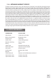
LIST OF CONTENTS TITLE Safety Summary List of Contents List of Figures List of Tables How to Use This Manual PAGE 2 4 5 6 6 1. INTRODUCTION 1.1 General Information 1.1.1 Type of Manual 1.1.2 Model Number and Equipment Name 1.1.3 Purpose of Equipment 1.1.4 Reporting Equipment Improvement Recommendations 1.2 Warranty Information and Registration 1.2.1 Warranty Information 1.2.2 Limitation of Liability 1.2.3 Product Warranty Registration 1.2.4 Obtaining Warranty Service 1.3 Cross References 1.
4. PREVENTIVE MAINTENANCE AND TROUBLESHOOTING 4.1 Preventive Maintenance Checks and Services 4.2 Operator Troubleshooting 4.3 Inspection Criteria for Proper Image Intensifier Tube Operation 4.3.1 Operational Defects 4.3.2 Cosmetic Blemishes 4.4 Maintenance 4.4.1 General 4.4.2 Cleaning Procedures 4.4.3 Battery Removal and Replacement 4.5 Return Instructions 29 29 31 31 31 32 34 34 34 34 35 APPENDIX A. Estimation of Ambient Illumination Level B. List of Spare Parts C.
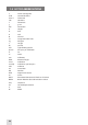
LIST OF Tables TABLE TITLE 2-1 2-2 2-3 2-4 2-5 2-6 2-7 2-8 2-9 2-10 3-1 3-2 4-1 4-2 A-1 B-1 System Description System Data Mechanical Data Electrical Data Optical Data Environmental Data IR850 Data Scope Mounting Systems Data Standard Components CO-Mini Optional Equipment CO-MINI Controls and Indicators IR850 Controls Preventive Maintenance Checks and Services Operator Troubleshooting Standard Natural Light Conditions and Illumination Values CO-MINI Spare Parts List PAGE 12 13 13 13 13 13 14 14 15 16 2
1 INTRODUCTION 1.1 GENERAL INFORMATION 1.1.1 TYPE OF MANUAL Operation and Maintenance (including a List of Spare Parts). 1.1.2 Model Number and Equipment Name Armasight CO-MINI Night Vision Clip-On System. Armasight CO-MINI MG Night Vision Clip-On System. 1.1.3 PURPOSE of Equipment The CO-MINI is a night vision system intended to be used for short to medium ranges (normally up to 350 yards) in conjunction with a daytime sight or riflescope (hereafter referred to as a “day scope”).
1.2 warranty INFORMATION and Registration 1.2.1 WARRANTY INFORMATION This product is guaranteed to be free from manufacturing defects in material and workmanship under normal use for a period of two (2) years from the date of purchase.
1.2.4 Obtaining Warranty Service To obtain warranty service on your unit, the End-user (Customer) must notify the Armasight service department via email. Send any requests to service@armasight.com to receive a Return Merchandise Authorization number (RMA). When returning any device, please take in the product to your retailer, or send the product, postage paid and with a copy of your sales receipt, to Armasight Corporation’s service center at the address listed above.
1.
2 DESCRIPTION AND DATA 2.1 System DESCRIPTION The CO-MINI consists of two primary parts: the night vision device (hereafter referred to as “NVD”), and the quick-release mount, or mount. The CO-MINI is delivered as shown in Figure 2-1: the mount (A) and top Weaver rail (B) should be secured on the NVD seating rails with M4×8 screws. B A Figure 2-1.
The automatic shut-off function preserves battery life in case the CO-MINI is inadvertently activated. The CO-MINI is powered by a single AA or CR123A battery. The CO-MINI uses a bi-color LED indicator to show the operator when the bright light protection system is activated, or to indicate a low battery. The Picatinny/ Weaver mount has an adjustable lever-cam clamping device for easy, quick and reliable mounting and removal of the CO-MINI. The CO-MINI is shown in Figure 2-2. The ITEM NO.
2.2 Specifications Table 2-2. SYSTEM DATA ITEM DATA Magnification Boresight Characteristics: — Accuracy — Retention — Repeatability System Resolution subject to Tube Resolution: — 45 to 54 lp/mm — 55 to 64 lp/mm — Over 65 lp/mm Unity (1X) Factory aligned to 2 MOA or better Permanent to within 4 MOA or better Within 2 MOA 0.65 mrad/lp 0.53 mrad/lp 0.45 mrad/lp Table 2-3.
Table 2-7. IR850 DATA ITEM DATA IR Emitter Type Peak Wavelength Half Width Divergence Battery Battery Life at 20 oC (68 oF) Overall Dimensions with Mount (L×W×H) Weight (with Mount, without Battery) Operating Temperature Storage Temperature Immersion MIL-STD-810 LED 850nm 20nm 6 to 20° Single CR123А (3V) 1.5 hr 121×41×37mm (4.76×1.61×1.46 in) 0.08 kg (0.18 lbs) -30 to +50°С (-22 to 122°F) -30 to +50°С (-22 to 122°F) 10m for 30 minutes Complies Table 2-8.
2.3 STANDARD COMPONENTS The CO-MINI standard components are shown in Figure 2-3 and listed in Table 2-9. The ITEM NO. column indicates the number used to identify items in Figure 2-3. 1 3 2 7 5 2 6 4 8 12 11 10 9 Figure 2-3. STANDARD COMPONENTS Table 2-9. STANDARD COMPONENTS ITEM no. DESCRIPTION QUANTITY 1 CO-MINI Night Vision Clip-On Device A night vision device intended for use in conjunction with a day scope. Mount for IR illuminator #60 A Weaver-type rail mounted to the CO-MINI.
table 2-9. continued ITEM no. DESCRIPTION QUANTITY 9 CR123А Battery A single lithium battery used to power the CO-MINI. A single lithium battery used to power the IR850. Special Wrench An instrument used for repositioning the adapter in the CO-MINI battery cap, depending on the battery being installed. Hard Case A protective case used for shipping/storage of the CO-MINI and its accessories.
table 2-10. continued ITEN NO. DESCRIPTION Scope Mounting System 2 #41 A mounting system used to install the CO-MINI on the lenses of specified day scopes. Includes a clamp with inserts that will fit 38 and 42mm diameters. Scope Mounting System 3 #42 A mounting system used to install the CO-MINI on the lenses of specified day scopes. Includes a clamp with inserts for 46.7, 48, 48.7-49, 49.5 and 50mm fitting diameters.
3 OPERATING INSTRUCTIONS 3.1 Installation and Mounting CAUTION: To protect the image intensifier tube when the device is not in use or when it is being operated in daylight, keep the protective objective lens cap securely fitted over the lens. 3.1.1 CO-MINI Battery Installation NOTE: At operating temperatures below -20°C (-4°F), alkaline battery life will be severely reduced. Under said conditions, the use of lithium battery is recommended.
Install the battery as follows (refer to Figure 3-1): 1. Unscrew the battery cap (C) and check the position of the adapter (D). See Figure 3-2 for the correct positioning of the threaded adapter, which changes depending on the battery being installed. 2. If necessary, change the adapter position in the cap. Use the special wrench. 3. Install the battery (B) into the battery compartment (A). Follow the battery symbol (E). 4. Replace the battery cap (C).
WARNING: Armasight recommends using an eyecup on the eyepiece of the day scope, allowing for the eyepiece diameter and eye relief and having side paddle preferably in order to escape detection. NOTE: The optical axes of the CO-MINI and the day scope should align. The distance between the axes should not exceed 2mm. If the difference in the axis heights of the CO-MINI and day scope above the weapon rail exceeds 2mm, you will need to replace the day scope mounting rings or monoblock.
LOCKED POSITION A UNLOCK POSITION B C Figure 3-6. MOUNT. UNDERSIDE VIEW 3.1.4 Clamping Device Adjustment Adjust the mount clamping device as follows (refer to Figure 3-6): 1. Unlock the clamping device and remove the CO-MINI from the weapon. 2. To tighten or loosen the clamping device, push the cam (C) towards the arrow. This will cause the nut (A) to slide out of the hollow. Turn the nut (A) CW/CCW respectively, in one-two increments (see note below).
The fully assembled CO-MINI with the raiser is shown in Figure 3-8. 3. To install the CO-MINI on a Picatinny/ Weaver rail in front of ACOG 4×32 scope, refer to Part 3.1.3. Figure 3-8. THE CO-MINI READY-ASSEMBLED WITH THE RAISER 3.1.6 Installing the CO-MINI ONTO the Lens of a Day Scope To install the CO-MINI onto a day scope, use the optional adapters. NOTE: The attaching diameters of the adapters differ, and must fit with the day scope parameters specified in Table 2-8 (Scope Mounting Systems Data).
2. 3. 4. 5. Take off the output lens cap and place it into the storage case. With the nut (B) loosened, position the insert (C) into the adapter’s clamp (A). Screw the adapter into the CO-MINI’s output lens thread. With the nut (B) loosened, slide the CO-MINI, with the adapter, onto the lens of the day scope as far as it will go. 6. Tighten the nut (B) with a screwdriver. NOTE: The second Weaver rail can be installed in place of the removed mount. A F B E D C Figure 3-10.
CAUTION: When loosening the ring (E), only utilize the two auxiliary, non-threaded holes (D). Avoid using the threaded ones. 4. Using a turning machine, cut the inside face of the ring (E). The value of cutting (in millimeters) is equal to the value of the turning angle (in angular degrees) divided by 360°. 5. With the cut end directed inwards, screw the ring (E) into the adapter’s body and tighten it. 6. Apply a small amount of thread lock to the threads. Affix the ring (E) with two M2×2.5 screws (F). 3.
3.2 Controls and Indicators CAUTION: DO NOT force the equipment controls past their stopping points. 3.2.1 CO-MINI Controls and Indicators The CO-MINI controls are shown in Figure 3-14. The CO-MINI controls and indicators are defined in Table 3-1. The ITEM NO. column indicates the number used to identify items in Figure 3-14. 2 3 1 Figure 3-14. CO-MINI CONTROLS Table 3-1. CO-MINI CONTROLS AND INDICATORS item no.
3.2.2 IR-850 Controls The IR850 controls are shown in Figure 3-15 and defined in Table 3-2. The ITEM NO. column indicates the number used to identify items in Figure 3-15. A B Figure 3-15. IR850 CONTROLS Table 3-2. IR850 Controls item no. CONTROL/INDICATOR FUNCTION 1 Power Switch Switches the IR850 on/ off and adjusts for radiated power. Four ‘on’ positions are located between two ‘off’ positions, and are each marked with a different-sized spot. The larger the spot, the greater the radiated power.
CAUTION: Avoid exposing the device to bright light sources such as firelight, headlights, searchlights, etc., as these can damage the CO-MINI. 5. To operate the CO-MINI in short-time activation mode, put the device in standby mode. To activate the CO-MINI, press and hold the remote control button. Release the remote control button to deactivate the CO-MINI. 6. Observe the scene. Adjust the image contrast by rotating the gain control knob (CO-MINI MG only). 7. If the day scope includes a focusing ring (i.e.
3.3.4 Shut-Down Shut-down the CO-MINI as follows: 1. Turn off the device. The green glow will disappear. 2. Place the cap over the objective lens. 3. Remove the CO-MINI from the weapon/day scope lens. 4. Remove the light suppressor from the output lens. 5. Screw the cap into the output lens thread. 6. Remove the IR850 from the CO-MINI. 7. Remove the batteries. CAUTION: Do not store the equipment with the battery still in it.
4 PREVENTIVE MAINTENANCE AND TROUBLESHOOTING 4.1 Preventive Maintenance Checks and Services (PMCS) Table 4-1: Preventive Maintenance Checks and Services has been provided so that you can keep your equipment operable and in good condition. Perform all functional tests in the order listed in Table 4-1. Operating Procedures are detailed in Chapter 3. Always observe any CAUTIONS that appear in the table. Explanation of Table Entries: SEQ NO. column.
table 4-1. continued SEQ. LOCATION/ITEM TO NO. CHECK/SERVICE PROCEDURE NOT FULLY MISSION CAPABLE IF... 8 Photoreceiver Inspect for cleanliness, scratches. Clean as required. Photoreceiver is damaged. 9 Remote Control Unit Check for damage. Check Velcro tape for wear. Damaged. Unit or tape is missing. 11 Light Suppressor Inspect for cuts or tears. Check ease of installation and removal. Light suppressor is torn or cut. 12 Mount Inspect for damage or corrosion, and for missing parts.
4.2 Operator Troubleshooting The purpose of troubleshooting is to identify the most commonly occurring equipment malfunctions, their probable causes, and the corrective actions required to fix them. Table 4-2 lists the common malfunctions that may occur during the operation or maintenance of the CO-MINI. Perform the tests, inspections, and corrective actions in the order listed in the table.
A. Shading If shading is persistent, you will not be able to see a fully circular image (Figure 4-1). Shading is a very dark, high-contrast area with a distinct line of demarcation present, and you cannot see an image through it. Shading always begins on the edge and will eventually migrate inward until it spans across the entire image area. If you notice shading with your device, please contact Customer Support. SHADING Figure 4-1.
A. Bright Spots A bright spot is a small, non-uniform bright area that may flicker or appear constant (Figure 4-3). Not all bright spots make the CO-MINI returnable. Cup your hand over the lens to block out all light. If the bright spot remains, please contact Customer Support. Bright spots usually go away when all light is blocked out. Verify that any bright spots are not simply the result of bright light in the area you are observing.
E. Chicken Wire Chicken Wire is an irregular pattern of dark thin lines that can appear in the field of view, either throughout the image area or in sections of the image area (See Figure 4-5). In the worst-case scenario, these lines will form hexagonal or square, wave-shaped lines. No action is required if this condition is present, unless it interferes with the user’s ability to view an image or their ability to perform missions. Figure 4-5. CHICKEN WIRE 4.4 Maintenance 4.4.
4.4.3 Battery Removal and Replacement Refer to Parts 3.1.1 and 3.1.2 for the CO-MINI and IR850 battery installation procedure, respectively. Replace the remote control batteries as follows: 1. Using a screwdriver, unscrew the four screws (A, Figure 4-6) that affix the cover to the bottom of the unit. Remove the cover. 2. Replace the batteries with two new ones (CR2016, 3V).
Appendix A. ESTIMATION OF AMBIENT ILLUMINATION LEVEL Table A-1 lists some common natural light conditions and their corresponding representative illumination values. TABLE A-1. Standard Natural Light Conditions and Illumination Values Standard Natural Light Conditions Illumination Value, lux Quarter moon 0.05 Full moon 0.30 Late twilight sky 1.00 Twilight sky 10.00 Overcast sky in the daytime 500.00 B.
TABLE B-1. CO-MINI LIST OF SPARE PARTS Item Description 1 2 3 4 5 6 7 8 9 10 11 12 Objective Lens Assembly Objective Lens Cap Turn-Push Switch Pivoted Shutter Battery Cap Battery Adapter (not shown) Battery Cap Retainer Purge Screw Gain Control Knob (CO-Mini MG only) Weaver Rail M4×8 Screw Mount C.
ALPHABETICAL INDEX A ABBREVIATIONS L 10 B LENGTH 13 M BATTERY INSTALLATION 18 MAINTENANCE 29 BLACK SPOTS 33 MOUNTING 18 BRIGHT SPOTS 33 O C OPERATING INSTRUCTIONS 18 OPERATIONAL DEFECTS 31 13 OPERATOR TROUBLESHOOTING 31 CHICKEN WIRE 34 P CLEANING 34 PMCS COSMETIC BLEMISHES 32 S CAUTIONS 2 CELL LIFE E 29 SAFETY SUMMARY 3 EDGE GLOW 32 SHADING EMISSION POINTS 33 SHUT-DOWN 28 SPARE PARTS 36 SYSTEM DESCRIPTION 11 F FIXED-PATTERN NOISE FLASHING, FLICKERING, OR I
Armasight Inc. 815 Dubuque Avenue, South San Francisco, CA 94080, USA Phone: (888)959-2259 Fax: (888)959-2260 Intl Phone/Fax: (650)492-7755 info@armasight.com CAUTION: This product contains natural rubber latex which may cause allergic reactions! The FDA has noted an increase in the number of reported deaths that are associated with an apparent sensitivity to natural latex proteins.