
Install Instructions


installation &
operating instructions
Astro 2, 3-speed
circulator models
4
These installation and operating instructions are applicable to the
following Astro 2 models.
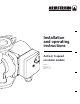
1.0 introduction
You are about to install a pump from the fi nest multi-speed wet
rotor circulator line on the market today. The Armstrong Astro
2 3-speed circulators are designed for closed hydronic or pota-
ble water systems. Their intended use is for circulating water or
glycol solutions. For pumping domestic water use non-ferrous
no lead bronze or stainless steel body pump construction.
The Astro 2 3-speed operates extremely quietly and is lubri-
cated by the system liquid being pumped by the circulator.
These circulators are designed to work at temperatures and
pressures up to 230°f (110°c) and 150 psi. For no lead bronze
and stainless steel pumps used in potable water systems, it is
recommended that the operating temperature of the fl uid be
kept as low as possible (i.e. below 150°f/66°c) to avoid precipi-
tation of calcium.
When unpacking the circulator, inspect for any damage that
may have occurred during transit. Check for loose, missing or
damaged parts.
2.0 installing
We recommend that any soldering be done before the pump
is actually installed. This will eliminate the possibility of solder
dropping into the pump body.
Thoroughly fl ush the system out before installing the circulator.
Before Installing, check that the fl ow direction of the water
through the pump body matches the arrow on the circulator
body. The circulator is supplied for up discharge installation.
Install the circulator in either the outlet or inlet line to the boiler
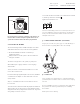
or hot water heater. It is important to install these circulators
with the split between the circulator body and the motor in a
vertical position. This ensures e cient operation.
See installation examples.
The circulator shaft must always be in a horizontal position.
(The piping can be in a horizontal or vertical run.) Isolation
valves should be installed on the discharge and suction side of
the pump to facilitate service.
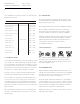
2.1 terminal box
Always install the circulator with the terminal box above or be-
side the motor. If the terminal box is under the motor as initially
mounted, remove the motor mounting screws and rotate the
motor to the proper position. (See example.)
Ensure the gasket is intact and seated before evenly retighten-
ing the mounting screw to 4.5 - 5.5 lb/ft (6 - 7.5 Nm). To ensure
the rotor still spins freely, temporarily remove the plug (located
in the middle of the nameplate), insert a fl at head screwdriver
into the slot in the end of the rotor shaft and turn.
Retighten the plug to 1.5 - 2 lb/ft (2 -2.7 Nm). Ensure no water
leak at all sealing contacts.
incorrect installationscorrect installations
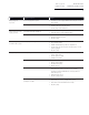
astro 2 models
model power supply rating
astro 220ssu
115v, 60hz
33w, 0.29a
astro 225ssu 83w, 0.69a
astro 225bs ½" swt 75w, 0.64a
astro 225bs O" swt 75w, 0.64a
astro 230ss 97w, 0.81a
astro 230ci 97w, 0.81a
astro 230ci-r 97w, 0.81a
astro 250ss 117w, 0.98a
astro 250ci 117w, 0.98a
astro 250ci-r 117w, 0.98a
astro 280ci 218w, 1.9a
astro 290ci 218w, 1.9a