
Install Instructions Control
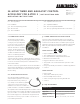

installation &
operating instructions
24-hour Timer and Aquastat
control accessory for Astro 2
2
technical data
Ambient Temperature
Range
-40°f to 180°f (-40°c to 82°c)
Power Consumption 120 V, 0.5 W
Supply Voltage 110-120 vac, 60 Hz
Terminals ¼" spade terminals
Weight Approximately 3 oz.
5.0 timer installation
warning
Electrical shock hazard - Verify that the electrical
rating of the device matches the values shown on the
nameplate of the circulator. All electrical work should
be performed by a qualified electrician in accordance
with the latest edition of the National Electric Code,
local codes and regulations. Failure to follow these
instructions could result in serious injury, death and/
or property damage.
warning
Risk of electric shock – This pump is supplied with
a grounding conductor and grounding-type at-
tachment plug. To reduce the risk of electric shock,
be certain that it is connected only to a properly
grounded, grounding-type receptacle.
Note: Steps 1 & 3 apply to retrofit installations.
1 Disconnect the electrical supply to the circulator
Note: Numerical component designations included in Steps
2 through 8 refer to circulator and timer components shown
in fig. 1.
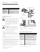
2 Unfasten the mounting 2 screws (4) and remove the terminal
box cover (3).
3 Disconnect wire leads from the power supply.
4 Connect power supply wires (black, white and green) to the
timer unit and to the circulator terminals (as shown in fig.2).
Note: Lead Wiring Specification - Minimum, 6" (152 mm)
long, 14 awg, rated minimum 140°f (60°c). Provided with r/c
crimp connectors for attachment to the ground.
5 Place the timer box cover (5) using the 2 mounting screws
(4). Insure that all lead wires are inside the timer assembly.
6 Program the timer according to instructions provided on
page 6.
7 Connect the unit to electrical supply.
8 Start the circulator.
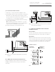
fig. 1 Astro 2 Series circulator and 24-Hour Timer assembly
drawing
fig. 2 Astro 2 Series circulator and 24-Hour Timer wiring
diagram
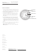
6.0 aquastat control accessory
*Temperatures indicated are at pipe surface
2
1
5
6
1. Pump
2. Terminal Box Base
3. Terminal Box Cover
4. Mounting Screw
5. Timer Box Cover
6. Timer Module Cover
Assembly - Exploded Layout
3
44
timer
white
white
white
green
green
black
black
black
black
black
G
Green Ground
Screw in timer box
technical data
Description Aquastat (thermostatic) switch
Type Surface sensing, snap acting bimetallic disc
Enclosure Environmentally sealed
Switch modes*
105 ± 5°f (40 ± 2°c) pump switches o
85 ± 6°f (29 ± 3°c) pump switches on
Contact position Normally open
Mounting
½": Clip-on type for X" o.d. system piping size
(i.e., ½" i.d. copper tubing or W" steel pipe)
O": Clip-on type for Y" o.d. system piping size
(i.e., O" i.d. copper tubing or ½" steel pipe)
May be mounted on either the inlet or outlet
piping of the circulator.
Lead length 14" (356 mm)