
Timer & Aquastat User Guide


installation &
operating instructions
24-hour Timer and Aquastat
control accessory for Astro 2
3
7.0 aquastat installation
1 Follow Steps 1, 2 and 3 in the Timer Installation section
2 The aquastat control is a surface temperature sensing device
that must be in contact with the system piping to operate
properly. Separate models include clip-on mounts for O" (Y"
o.d.) and ½" (X" o.d.) copper tubing. (See fig. 3)
3 Connect the black, green and white lead wires according to
the wiring diagram (fig. 4)
Note: Lead Wiring Specification - Minimum, 6" (152 mm)
long, 14 awg, rated minimum 140°f (60°c). Provided with r/c
crimp connectors for attachment to the ground.
4 Close the terminal box cover and fasten the screw
fig. 3
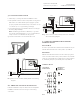
fig. 4 Astro 2 Series circulator with Aquastat Control wiring
diagram
8.0 timer and aquastat installation
Follow the installation steps in both the Timer and Aquastat
installation instructions and refer to Fig. 5 for the wiring
connections.
fig. 5 Astro 2 Series circulator with 24-Hour Timer and Aqua-
stat Control wiring diagram
9.0 timer programming with manual
override switch
Automatic Mode
In order to operate the time switch in the automatic mode, the
manual switch must be in the center position. (See fig. 6)
Manual Mode
With the manual switch selector lever the selected programs
can be overridden. In the lower position, marked "o", terminals
3 and 5 are permanently closed. In the upper position, marked
"i", terminals 3 and 4 are permanently closed. (See fig. 6)
override mode
fig. 6
white
pump
white
aqu
astat
black
black
green
G
aquastat
timer
white
white
white
white
black
black
black
black
black
black
green
G
Green Ground
Screw in timer box
on
3-way manual
override switch
permanent on
automatic
permanent o
on
o
o