
Replacement Part Install Instructions


installation &
operating instructions
e.2 Series mechanical
seal replacement
5
15 Remove the installation tool from the shaft.
16 Install the impeller keeping the inlet end up. Make sure to
align the fl ats to the shaft fl ats and push the impeller down
tightly to the seal.
17 Place 2-3 drops of medium strength thread locker liquid on
the nut threads.
18 Install the special left hand thread nut on the motor shaft.
While holding the motor rotor in place as in step 3, thread
the impeller nut on to the shaft in a counter-clockwise
direction and tighten the nut to approximately 6ft-lbs.
19 If the impeller will not spin freely contact Armstrong
Technical Support at 1-416-755-2291 or email
techsupport@armlink.com.
20 Ensure the gasket is properly seated in the pump casing
(volute) gasket groove. Holding the motor body, insert
the impeller straight into the volute. Verify the gasket was
not dislodged during insertion, and is still seated properly.
Hold the motor body steady while fastening the four bolts
that attach the motor to the pump casing (volute). Tighten
evenly and diagonally. There should be a small, even gap
of about 0.02" (0.5 mm) between the motor fl ange and the
pump casing (volute).
21 Follow the start up instructions (File no. 10.84)
and check for leaks.
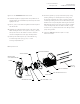
casing
impeller nut
(left hand thread)
mechanical seal
impeller
seal seat and l-cup
casing gasket
faceplate
housing extender
motor assembly
motor
bolt (4)
seal installation tool
fi g.1 Exploded view