Bulletin 539-A HumidiClean™ Series HC- 6100/6300/6500/6700 Humidifiers Installation, Operation and Maintenance Instructions Table of Contents Page Warning Labels Description of Model Number Installation Display Menu Start-Up Procedure and Operation Maintenance Troubleshooting Typical Wiring Schematic Repair Parts Software Update Communication Warranty Please read and save these instructions.
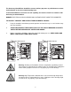
The Armstrong HumidiClean humidifier converts ordinary tap water or purified water to steam for distribution to raise the relative humidity level. To allow HumidiClean to function to its full capability, be certain to install in accordance with Armstrong recommendations. DANGER: ELECTRICAL SHOCK HAZARD HIGH VOLTAGES EXIST INSIDE THE HUMIDIFIER TO PROTECT YOURSELF AND OTHERS FROM ACCIDENTAL SHOCKS: 1.
Warning: Do not operate the supplied humidifier in combustible or explosive surroundings. Warning: Do not operate the supplied humidifier if there is any damage to the cabinet or any components in humidifier are damaged. Warning: The main switch should be a connection breaker which has over current and leakage current protecting functions per code EN60947-3 or EN60947-2 if point gap required by EN60947-3 can be fulfilled. 4.
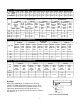
• This disconnecting switch should have leakage current protecting function. The max leakage current should be less than 30mA • The disconnecting switch should have a breaking capacity sufficient to interrupt the largest normal running current of loads. The breaking capacity required should be selected according to the table, 7-1, 7-2, 7-3 and 7-4 located on page 7.
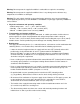
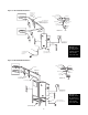
Figure 5-1 HC-6100/6300 Installation Pitch Min. 1” Per 12” Back to Unit Hose Clamp Steam Hose or Copper Full Size Tee See Detail “A” Hose 2” Insulated Copper “P” Trap Drain Every 20’ of Piping or at Bottom of Vertical Run 2” Copper Tee Soldered Joints Reducer 1/2” or 3/8” Copper Tube UP 6” Min. Detail “A” Pitch Min.
Installation HC-6100/6300 Mounting The HumidiClean models HC-6100/6300 are designed to be wall mounted. A wall mounting bracket and lag screws are provided for mounting on 410 mm (16”) centers. The operating weight of the unit is 106 kg (233 lbs). A clearance of 600 mm (23”) on the front and sides of the cabinet is required for servicing. 1. Position wall mounting bracket level on wall and mark hole pattern. Make sure holes line up with studs or other sturdy structure. 2.
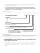
Table7-1. 7-1.Recommended Recommended Branch Circuits Table Branch Circuits Rating Amp (AWG) Wire (mm2) Circuit Breaker 1-12 14 3 15 13-15 12 4 20 16-20 10 6 25 21-24 10 6 30 25-32 8 10 40 33-40 8 10 50 41-48 6 16 60 49-64 4 25 80 68-80 3 35 100 81-100 1 50 125 101-120 0 50 150 121-140 0 70 175 141-60 0 95 200 Table 7-2. 7-2.
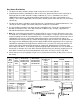
Duct Steam Distribution 1. The dispersion tube should be proper length. Verify correct size from Table 8-1. 2. Install dispersion tube(s) horizontally in duct so holes face upward. Air flow must be vertical up or horizontal. Do not restrict duct with a height of 200 mm (8”) or less. Installations over 10 m/s (2000 FPM) air velocity are not recommended. Consult factory if air flow is vertical down or air velocity is over 10 m/s (2000 FPM).
Area Steam Distribution The EHF-3 fan package (minimum of 2 required for HC-6500/6700) is designed to be hung on a wall to operate as a remote mounted, direct area discharge option. It incorporates a blower rated at 120v2.90 amps. CFM rating is 465 @ 1530 RPM. The fan package requires a separate 120 volt power supply (optional step down transformer available). Consult Armstrong Installation Bulletin IB-95 for more information.
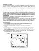
Figure 10-1 Standard Humidistat H200-XX-XX-XX Supply Main Stat/Sensor In Modulating High Limit Sensor Outdoor Temperature Sensor A18609 or A18610 0-10 Vdc Stat (Standard) Ground Class 2 Alarm A8581 High Limit Humidistat High Limit/ Air Flow Switch Ground A9023 Pressure Switch To Set Up: 1) S1-1, 3 Off, S1-2 On 2) S3-1 On, S3-2, 3, 4 Off 3) S2-1, 2, 3 Off 4) Select 0-10vdc “Signal Type” in the Operational Setup Menu. 5) Select Humidistat Sensor Select in the Operational Setup Menu.
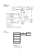
Figure 11-1 0-10 Vdc or 4-20mA Control Signal Supply Main Stat/Sensor In Modulating High Limit Sensor Control Signal Outdoor Temperature Sensor Ground S5079a,b,c 4-20ma Setup 10 vdc Setup 1) S3-1 On, 3-2, 3, 4 Off (Default) 2) S1-2 On, S1-1, 3 Off (Default) 3) S2-1 On, S2-2, 3 Off if 4-20ma S2-1, 2, 3 All Off If 0-10vdc 4) Select Corresponding Control Signal Type In Operation Setup Menu.
High Limit Humidistat Remove the jumper tab from ground and in of high limit/pressure switch connections and wire the high limit stat between these terminals. Refer to Figure10-1 (the overall wiring diagram) for more inform ation. A duct mounted high limit humidistat is recommended to prevent over-saturation of the duct air. Use an on-off controller that opens on fault (high humidity). Humidistat should be set for a maximum of 90% RH.
Display Menu The menu can be accessed via the keypad below the LCD, on the front of electric cabinet. Use the UP or DOWN to change the menu in current level; press ESC to previous menu level; press ENTER to access the current menu. Pressing ENTER will activate selection cursor, press UP(DOWN) to increase (decrease) the value, press ENTER to confirm the change or ESC to cancel.
Operation Setup Operation Setup Enter Password 0000 (Default) This menu is displayed when RH sensor is selected Desired RH Desired RH: XX % Default: 50% Current RH: XX% LT RT move the cursor UP DN to increase/decrease value Steam Generation Steam Gen (Default) Manual Drain Manual Fill Unit Stop Modulating Fill Cycle Enabled (Default) Disabled If modulating fill cycle is enabled: Fill Valve Off Time 30 seconds Fill Valve On Time 10 seconds Error Reset Error Reset? Error Reset Confirm Cancel Aquastat Te
Operation Setup Operation Setup -- Continued Continued Drain Frequency Default: 12 hours 6 12 (Default) 24 48 96 No Drain Real Time Real Time Set 24 Hour Clock Drain Time 1 5 (Default) 10 Load Default Reset all to Default? Confirm Cancel Signal Type 0-10 Vdc (Default) 0-5VDC 1.9V - 3.
Unit Configuration Enter Password ARMH Run Mode Run (Default) Test Contactor Count 1 2 3 4 Control Type PWM (Default) On/Off Power Settings 1000 W 3000 W 5000 W 6650 W 8000 W Ionic Time Reset Clear Ionic Time Confirm Cancel Error Record Clear Clear Error List Confirm Cancel User Password Reset User Password Reset Confirm Cancel Temperature Compensation Water Compensation Heater Compensation Factory Use Only Start-Up Procedure (Before “Power On”) 1.
Principle of Operation The HumidiClean humidifier converts ordinary tap water or purified water to steam for distribution to raise the relative humidity level. The demand for humidity is sensed by a humidistat or sensor which sends a control signal to the HumidiClean. The HumidiClean is connected to the power supply (208, 220/240, 380/400, 480 or 600 Vac) through a separate circuit breaker supplied by the customer.
Completing a Service Life Cycle When 90% of the setting service time has accumulated, the "STATE" LED on the control panel will blink in yellow. (Refer to EOL settings, for bed life duration settings). If the HumidiClean is not serviced at this time; the unit will continue to operate for the remaining 10% of the service life setting. When 100% of the bed life setting has been reached, the "STATE" LED will be on in red. The unit will drain the tank and not respond to a call for demand. A.
5) Restoring the Unit to Operation a) Turn power on at breaker. b) Unit should begin to fill. Maximum fill time is approximately 30-45 minutes before contactor(s) will be closed. c) If this does not take place, operate the menu, and change the status to "STEAM GEN." B. Modifying the Bed Life Setting 1) Complete the steps for servicing the unit as outlined above. 2) Change the EOL settings to desired value in Unit Status menu. 3) Save settings in menu.
Figure 20-1 HC-6100/6300 Steam Outlet Equalizing Connection to Top of Level Canister Cover Locating Pins Ionic Beds Equalizing Connection to Bottom of Level Canister Heating Elements Drain Oulet Connection Mounting Bolt Locations Figure 20-2 HC-6500/6700 Steam Outet Equalizing Connection to Top of Canister Cover Locating Pins Ionic Beds Equalizing Connection to Bottom of Level Canister Heating Elements Drain Outlet Connection Mounting Bolt Locations 4.
9. Operate the unit configuration menu “Ionic Time Reset”, to reset the ionic bed life. All the accumulated ionic bed time has been reset to zero. The unit should now be heard filling. NOTE: The accumulated ionic bed time can be reset to zero at anytime. However, the unit should not be reset without first inspecting the ionic beds. 10. After the unit has heated up and started making steam, turn main power off and double check tank access panel gasket for steam leakage.
Removing the Tank, HC-6100/6300 Only 1. Operate menu to "MANUAL DRAIN" and allow unit to complete a deep drain. (Caution: Tank will still be quite warm). 2. Turn off circuit breaker. 3. Unlock and open front and side doors. Remove left side panel. 4. Disconnect 3 hoses from front of tank; rubber hose cuff at steam outlet; heating element leads at contactor, fuses, or power module; and thermocouple wires. 5. Loosen and remove 2 mounting bolts at the bottom of tank.
8. If drain valve and fill valve are both energized and water is below the 1/3 full level in the electrode canister (float canister for DI units), make sure the status of Steam Generation in menu is "STEAM GEN.". Perform continuity check to be sure. 9. If drain valve only is energized and water level is below the 2/3 full level in electrode canister (float canister for DI units), there may be excessive debris in electrode canister (float canister for DI units). Inspect and clean if needed.
4. If fuses are OK, check voltage to contactor coil. (a) If voltage is 24-28VAC at contactor coil, check coil resistance. It should be 8Ω with wires disconnected. If resistance is OK, check voltage drops across the contactor. (b) If no voltage to contactor coil, check continuity of wires from PC board to contactor. If continuity is OK, PC board is likely defective. 5. Check voltage signal to power module. The voltage across TAB8-1 and TAB8-2 (low voltage signal to power module) should be 12 Vdc.
Humidifier runs continuously, %RH is well under set-point. 1. Verify humidistat/RH sensor is wired correctly and dip switches (S2 & S3, See Fig. 10-1, 11-1 and 11-1) on the PC board are set correctly for the humidistat signal. 2. Check humidistat demand signal at low voltage terminal strip. It should be close or at 100%. 3. If humidifier is a three phase model, verify all three phases of power are present and equal. 4. Check amperage draw on all high voltage power lines with a clamp on amp meter.
Dispersion tube spits water or water is present in duct Hint: It is very helpful to cut a small observation window in the duct and cover it with Plexiglas so the steam discharge from the manifold can be observed. This way the problem can be narrowed down to piping/steam quality (steps 1 and 2) or a condensation problem (steps 3 and 4). 1. Check distribution piping for proper pitch and size. Make sure there are no loops, dips or sags where pockets of water can collect.
2 WATER LEVEL DROPPED BELOW LOW LEVEL - - The low level switch has not closed after 5 minutes of fill valve on time. This is only after initial start-up fill and boil-down sequence. Check: debris in water switch canister, defective fill valve, no water flow or low water pressure, drain valve stuck open, defective low water level switch (electrodes need to be cleaned).
HC6100-Wye Wiring layout 28
HC6100-Delta Wiring layout 29
HC6100-PAR Single Phase Wiring Layout 30
HC6300-Wye Wiring layout 31
HC6300-Delta Wiring layout 32
HC6500-Wye Wiring layout 33
HC6500-Delta Wiring layout 34
HC6500-WYE (2 contactors) Wiring Layout 35
HC6500-Delta (2 contactors) Wiring Layout 36
HC6700-Wye Wiring layout 37
HC-6000 Repair Parts Item Item No. No. 31 16 1 — — 32 14 12 11 6 7 5 13 13 13 13 8 8 8 8 8 3 3 4 4 ElectricalCompartment Compartment and Panel Electrical andFront Front Panel Label Front Panel With Keypad Emergency Stop Button (2 N.O.
HC-6100 3kW Voltage 208 240 380 480 600 HC-6100 Without TC 2PCS/Unit B5808-1 B5808-2 B5808-1 B5808-3 B5808-4 3kW DI With TC 1PCS/Unit B5809-1 B5809-2 B5809-1 B5809-3 B5809-4 Without TC 2PCS/Unit B5810-1 B5810-2 B5810-1 B5810-3 B5810-4 9kW Voltage 208 240 380 480 600 HC-6100 DI Without TC 2PCS/Unit B5047-1 B5047-2 B5047-1 B5047-3 B5047-4 15kW With TC 1PCS/Unit B5048-1 B5048-2 B5048-1 B5048-3 B5048-4 Without TC 2PCS/Unit B5043-1 B5043-2 B5043-1 B5043-3 B5043-4 9kW Voltage 208 240 380 480 600 HC-6300
Item Item No. No. Electrical Compartment Compartment Electrical and Front Front Panel and Panel Part Part No. No. Item Item No. No.
HC-6000 Repair Parts Resistance Value of 6100/6300 Components Component Resistance Value of 6500-6700 Comoponents Voltage Resistance Component Voltage Resistance Fill Valve 24Vac 18Ω Fill Valve 24Vac Drain Valve 24Vac 10Ω Drain Valve 24Vac 8.8Ω 4.1Ω Contractor 24Vac 7-9Ω Thermocouple in Heating Elements - 0.51Ω Thermocouple in Heating Elements Heating Elements - 0.51Ω Heating Elements 208Vac and 380Vac 3kW 220 Vac 46.0-48.
HC-6000 Repair Parts HC6500/HC6700 Voltage 208 204 380 480 600 HC6500/HC6700 45kW 30kW 33.5kW 40kW Without TC With TC Without TC With TC Without TC With TC Without TC With TC 5PCS/Unit 1PCS/Unit 5PCS/Unit 1PCS/Unit 5PCS/Unit 1PCS/Unit 8PCS/Unit 1PCS/Unit B5433-1 B5434-1 B5433-1 B5434-1 B5433-1 B5434-1 B5433-1 B5434-1 - 48kW 50.
Procedure of HC6000 Version 7 Soft Refresh This section is used for HC6000 software reprogramming only. Please follow the instructions carefully, or pc board could become un-functional. 1. Install the driver program for Atmel MCU, SAM-BA on your computer first. The link for the Atmel program AT91-ISP.exe and the latest version of can be found at the following location: www.armstronginternational.com/hc6000refresh 2. Before refreshing the code, the old code in CPU must be erased: a.
Fig.2 Code Download Window d. Click the "open folder" button on the right of textbox "Send File Name" to open the latest code, please see figure 3 below. You will then have to locate the .bin file that you downloaded from the website and then hit open. Fig.
e. Click the button "Send File" to send the latest code into board. You will be asked to unlock the involved lock regions (0 to 7), click the button "Yes" to begin send code into board. Please see figure 4 below. Fig.4 Message Unlock Involved Lock Regions Window f. When sending was finished, you will be asked to lock all locks that you have opened just now, click the button "Yes" to lock these locks. You can verify that the code was send to the board by scrolling up in the message box. See Figure 5 below.
g. When operation has finished, close the "SAM-BA" window first, and then click the icon "remove the USB hardware" to disconnect the link between computer and board. After reminder by system, disconnect the power supply from breaker and pull out the USB cable. h. The soft refresh of HC-6000 is complete restart the unit. Introduction to Communications HC6000 series provides two types of remote communication port: RS-485 and RS-232.
Table 46-1 Modbus Variable Lists data type attribute bit read only bit read write 16 bit read only data address 10001 10002 10003 10004 10005 10006 10008 1 2 3 4 5 6 30001 30002 30003 description Fill valve status 0:off 1:on Drain valve status 0:off 1:on contactor 1 status 0:off 1:on contactor 2 status 0:off 1:on contactor 3 status 0:off 1:on contactor 4 status 0:off 1:on Network control 0:Local 1:Remote comm type 0:485 1:PSP Sensor select 0:Humidistat 1:RH sensor High limit sensor select 0:not use
Table 47-1.
Table 48-1.
Physical Data, Capacities and Dimensional Drawings Figure 49-1. Models HC-6100 and HC-6300 D K 1” Drain E Electrical Supply G M Knock-Out for Humidistat L A H Knock-Out for Humidistat C F H B R J Table 134-1.
Physical Data, Capacities and Dimensional Drawings Figure 135-1.
Armstrong International, Inc. Limited Warranty and Remedy Armstrong International, Inc. ("Armstrong") warrants to the original user of those products supplied by it and used in the service and in the manner for which they are intended, that such products shall be free from defects in material and workmanship for a period of one (1) year from the date of installation, but not longer than 15 months from the date of shipment from the factory, [unless a Special Warranty Period applies, as listed below].