Date: 10/01/07 OWNERS MANUAL CUMMINS SERIES: MODELS A50CU, A75CU, A05CU, A200CU, A300CU, A400CU, A500CU, A600CU, A830CU, A1000CU SAVE THESE INSTRUCTIONS This manual contains important instructions regarding for all Armstrong Power Systems LLC power generator Models. The information contained here must be followed during installation and maintenance of the generator and batteries.
Page 2 SAVE THESE INSTRUCTIONS This manual contains important instructions regarding for all Armstrong Power Systems LLC power generator Models. The information contained here must be followed during installation and maintenance of the generator and batteries. Keep this manual with the equipment. If the equipment is traded or sold, give the manual to the new owner. You are now the owner of a Armstrong Power generator powered by CUMMINS engine.
Page 3 WARRANTY CERTIFICATE The warranty period for the power generator begins on the date of sale and continues for a period of 2 years or 1500 hours (what ever comes first). Responsibilities: a) As the owner, you are responsible for the performance of the required maintenance listed on your operators manual. b) Armstrong Power may deny your warranty coverage if your engine or part has failed due to abuse, neglect, improper maintenance or unapproved modifications.
Page 4 AR-EXP-CUMMINS-07-00 OWNERS MANUAL
Page 5 1. INTRODUCTION This manual provides general safety information for installing, operating and maintenance of Armstrong Power equipments. The purchaser should comply with the instructions and information in this manual, and is strongly advised that all personnel to be associated with the equipment supplied should be made familiar with the information contained herein.
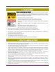
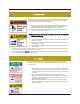
Page 6 3. FIRE AND EXPLOSION Risk of serious injuries or death Fuels and fumes associated with generating sets can be flammable and potentially explosive. Proper care in handling these materials can dramatically limit the risk of fire or explosion. However, safety dictates that fully charged BC and ABC fire extinguishers are kept on hand. Personnel must know how to operate them. The acids in the battery can cause explosion.
Page 7 5. MECHANICAL The generating set is designed with guards for protection from moving parts. Care must still be taken to protect personnel and equipment from other mechanical hazards when working around the generating set. Do not attempt to operate the generating set with safety guards removed. While the generating set is running do not attempt to reach under or around the guards to do maintenance or for any other reason.
Page 8 7. NOISE Generating sets that are not equipped with sound attenuating enclosures can produce noise levels in excess of 105 dBA. Prolonged exposure to noise levels above 85 dBA is hazardous to hearing. Ear protection must be worn when operating or working around an operating set. 8. ELECTRICAL Safe and efficient operation of electrical equipment can be achieved only if the equipment is correctly installed, operated and maintained.
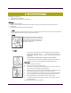
Page 9 9. FIRST AID FOR ELECTRIC SHOCK Identification / look out for: Unconsciousness and Burns Establish site of entry and exit of electric shock What to do: Switch off the main switch. Break the contact between electrical source and patient using dry non-conductive object like wooden stick. Call for help. If breathing and heartbeat has stopped begin CPR 1. CALL Check the victim for unresponsiveness. If there is no response, Call 911 and return to the victim.
Page 10 10. SPECIAL CONSIDERATIONS FOR BATTERY CAUTION – The electrolyte is a dilute sulfuric acid that is harmful to the skin and eyes. It is electrically conductive and corrosive.
Page 11 GENERATING SET INSTALLATION AR-EXP-CUMMINS-07-00 OWNERS MANUAL
Page 12 1. LOCATION The generating set sub base tank or frame (if it‘s the case) is specifically designed for ease of moving the set. Improper handling can cause serious damage to the generator and components. Never lift the generating set by attaching lugs to the engine or alternator. Shackles and chains of suitable length and lifting capacity must be used. A spreader bar is required to prevent damaging the set.
Page 13 Concrete foundations are typically mixed by volume. The typical ratio of cement, sand, and aggregate is 1:2:3 with a maximum 4 inch (102 mm) slump and 28 day compressive strength of 2500 psi (173 kPa).
Page 14 people will not be endangered. Besides the possibility of carbon monoxide poisoning, exThere are a number of different generator systems and haust piping becomes extremely hot during operation and typical loads in the context of electrical systems. Most sys- remains hot for a long time after shutdown.
Page 15 6. INSTALLATION CHECKLIST BATTERY INSTALLATION ❏ Battery is connected properly. ❏ Recommended battery is installed. ❏ Cables are clean and tight. ❏ Terminals are coated with anti-corrosion grease, and terminal covers are positioned. FUEL SYSTEM ❏ Complies with local and NFPA codes. ❏ Fuel is connected and checked for leaks. ❏ Correct fuel pressure (11-14 inches of water (0.6 psi) at all load ranges). ❏ Load block adjusted for maximum power for natural gas fuel.
Page 16 GENERATING SET OPERATION AND MAINTENANCE AR-EXP-CUMMINS-07-00 OWNERS MANUAL
Page 17 7. PRE-OPERATION CHECK BREAK-IN During the engine break-in period, observe the following by all means: Change engine oil and oil filter cartridge after the first 50 hours of operation 2. DAILY CHECK To prevent trouble from occurring, it is important to know the conditions of the engine well. Check it before starting. CAUTION To avoid personal injury: • Be sure to install shields and safeguards attached to the engine when operating. • Stop the engine at a flat and wide space when checking.
Page 18 the start was initiated by remote start), the return delay timer is initiated after which the load Transfer signal is deenergized, removing the load. ¾ second later, the mains load switch is closed, returning the mains on load. If the generator set has been on load, The Cooling timer is then initiated, allowing the engine a cooling down period off load before shutting down. 7.3.
Page 19 BATTERY CHARGE FAILURE cur. The icon will illuminate. OVERSPEED / OVERFREQUENCY If the engine speed exceeds the pre-set trip a shutdown is If the module does not detect a voltage from the warning initiated. The icon will illuminate. Overspeed is not delayed, light terminal on the auxiliary charge alternator the icon will it is an immediate shutdown. illuminate.
Page 20 Typical LCD screens LCD Display Areas Instruments The LCD displays the various engine parameters such as ‗ENGINE SPEED‘, ‗OIL PRESSURE‘, ‗HOURS RUN‘, etc. Each instrument is displayed with the appropriate units of measure. In this example, the values being displayed are Generator phase to phase AC voltages Alarm Icons The LCD also displays the exact nature of any alarm condition that may have occurred such as LOW OIL PRESSURE using appropriate icons.
Page 21 It is possible to manually scroll to display the different instruments by repeatedly operating the scroll button. Once selected the instrument will remain on the LCD display until the user selects a different instrument or after a period of USER CONFIGURABLE LCD INDICATORS inactivity the module will revert to the initial display (Hz/ RPM).
Page 22 then be removed the generator will remain on load until either the ‗STOP/RESET‘ NOTE:- Configuration mode can ONLY be entered when the or ‗AUTO‘ positions is selected. module is in the STOP mode and the engine is at rest. Press the DOWN and STOP buttons to enter configuration mode. Auto This button places the module into its ‗Automatic‘ mode. This mode allows the module to control the function of the generator automatically.
Page 23 ton will cancel any changes made to the current parameter, reverting to the last ‗saved‘ value. This also exits adjust mode. NOTE:- To exit the front panel configuration editor at any time press the STOP button. Ensure you save any changes you have made by pressing the button first if necessary. Timers and Analogue Settings NOTE:- Setting a timer to zero (0) will disable it. Timer settings increment from 0 to 60s in steps of 1s and from 1 minute to the maximum value in steps of 30 seconds (0.
Page 24 7.6 Panel Trouble Shooting NOTE:- The above fault finding is provided as a guide check-list only. As it is possible for the module to be configured to provide a wide range of different features always refer to the source of your module configuration if in doubt.
Page 25 8.
Page 26 AR-EXP-CUMMINS-07-00 OWNERS MANUAL
Page 27 FG MOLDED CASE 15-150 AMPS AR-EXP-CUMMINS-07-00 OWNERS MANUAL
Page 28 JG MOLDED CASE 175-250 AMPS AR-EXP-CUMMINS-07-00 OWNERS MANUAL
Page 29 AR-EXP-CUMMINS-07-00 OWNERS MANUAL
Page 30 KG MOLDED CASE 300-400 AMPS AR-EXP-CUMMINS-07-00 OWNERS MANUAL
Page 31 AR-EXP-CUMMINS-07-00 OWNERS MANUAL
Page 32 LG MOLDED CASE 450-600 AMPS AR-EXP-CUMMINS-07-00 OWNERS MANUAL
Page 33 AR-EXP-CUMMINS-07-00 OWNERS MANUAL
Page 34 MG MOLDED CASE 700-800 AMPS AR-EXP-CUMMINS-07-00 OWNERS MANUAL
Page 35 AR-EXP-CUMMINS-07-00 OWNERS MANUAL
Page 36 NG MOLDED CASE 900-1200 AMPS AR-EXP-CUMMINS-07-00 OWNERS MANUAL
Page 37 1600-2500 AMPS AR-EXP-CUMMINS-07-00 OWNERS MANUAL
Page 38 9. ENGINE 9.1. CHECKS DURING OPERATION Air Tank and Reservoirs - Drain Cooling Fan - Check/Correct Crankcase Breather Tube - Inspect Drive Belts - Check/Correct While running, make the following checks to see that all parts are working correctly.
Page 39 Table 1: Jacket Water Cooled, Turbocharged Only, or Naturally Aspirated Engines Cummins Engine Standard Classification American Petroleum Institute International Classifications Classification (CES) (API) All Engine Ratings CES-20078, CES-20077, CESAPI CI-4/SK, API CI-4, API 20076, CES-20072, CESCH-4, API CH-4/SJ 20071 ACEA E-5, Global DHD-1 250 Hours or 3 Months CES-20075 API CF-4/SG ACEA E-3, ACEA E-2, JAMA DH-1 150 Hours or 6 Weeks API CG-4/SH, API CD, API CE ACEA E-1 Obsolete.
Page 40 WARNING Do not mix gasoline, alcohol, or gasohol with diesel fuel. This mixture can cause an explosion. CAUTION Due to the precise tolerances of diesel injection systems, it is extremely important that the fuel be kept clean and free of dirt or water. Dirt or water in the system can cause severe damage to both the fuel pump and the fuel injectors. Cummins Inc. recommends the use of ASTM number 2D fuel. The use of number 2 diesel fuel will result in optimum engine performance.
Page 41 The use of quality engine lubricating oils, combined with appropriate oil drain and filter change intervals, is a critical factor in maintaining engine performance and durability. Cummins Inc. recommends the use of high-quality SAE 15W-40 heavy-duty engine oil, such as Valvoline® Premium Blue®, which meets performance specifications as listed below.
Page 42 Water Quality Calcium Magnesium (hardness) Maximum 170 ppm as (CaCO3 + MgCO3) Chloride 40 ppm as (CI) Sulfur 100 ppm as (SO4) Cummins Inc. recommends using Fleetguard® Compleat. It is available in both glycol forms (ethylene and propylene). Fully formulated antifreeze must be mixed with good-quality water at a 50/50 ratio (40- to 60-percent working range).
Page 43 In case of complete overhaul of genset, the bearing of the generator should be changed. On request prelubricated bearings with regreasing system can be mounted. When regreasing use 20/ 30 grams of grease. Following types of grease are to be recommended for normal application: MOBIL OIL: MOBILUX 3 SHELL: ALVANIA 3 AGIP: GR MW 3 ESSO: BEACON 3 10.3.