Bulletin 527-G Installation and Maintenance Series EHU-700 Humidifiers Please Read And Save These Instructions The Armstrong Series EHU-700 humidifier is an electronically controlled, non-pressurized steam-generating humidifier, with its vapor discharged into a duct of an air-handling system or through a fan package. The Armstrong Series EHU-700 consists of three models: The EHU-701, 703 and 704. The maximum capacity of the series is 240 Ibs/hr.
DANGER ELECTRICAL SHOCK HAZARD HIGH VOLTAGES EXIST INSIDE THE HUMIDIFIER To protect yourself and others from accidental shocks: 1. Keep the humidifier locked during normal operation and store the key in a safe location away from the humidifier. 2. ALWAYS DISCONNECT THE POWER SUPPLY AT THE CIRCUIT BREAKER OR SAFETY SWITCH BEFORE OPENING ANY COVERS! 3. Before servicing the humidifier, learn where the high voltage parts are.
TABLE OF CONTENTS SECTION 1: PREPARATION AND INSTALLATION WARNINGS.................................................................................................................. PRE-INSTALLATION................................................................................................... Check shipment................................................................................................ Check local codes.......................................................................................
PRE-INSTALLATION 1) CHECK SHIPMENT A claim should be filed with the transportation company (and reported to Armstrong) if any items are missing or damaged. Your shipment will arrive in two or three cartons. One carton holds the humidifier with the steam generator installed, the control humidistat and sensing element, two short steam hoses, hose clamps, mounting plate and lag screws, and a clear drain hose.
The mounting surface should be a wall capable of supporting the maximum humidifier weight. The maximum operating weight is: Model unit 701 703 704 Water 60 Ibs. + 20 Ibs. 83 Ibs. + 30 Ibs. 95 Ibs. + 60 Ibs. = = = Total 80 Ibs. 113 Ibs. 155 Ibs. The location chosen should be inside with a minimum ambient temperature of 40°F. and a maximum of 100°F. The humidifier should not be mounted on hot surfaces.
INSTALLATION 4) MOUNTING THE HUMIDIFIER MODEL EHU-701: Making sure the unit is level, hold it against the mounting surface and mark the hole pattern. Attach the units to studs or other sturdy structure with the two 3/8"× 1½" lag screws provided. MODELS EHU-703 & 704: Making sure the mounting bracket is level, attach it to studs or other sturdy structure with the two 3/8"× 1½" lag screws provided. Hang the humidifier on the mounting bracket.
6) WATER FILL SUPPLY Connect the unit to the building water supply (25 to 125 psig pressure). Install a shut-off valve near the humidifier. Connect the water supply to the 3/8" tube compression fitting on the fill valve adaptor. NOTE: ORDINARY (POTABLE) TAP WATER IS RECOMMENDED. IF POTABLE WATER IS NOT AVAILABLE, CONSULT THE FACTORY (SEE "WATER QUALITY AND TREATMENT SECTION OF THIS MANUAL, PAGE 23, FOR MORE INFORMATION). DO NOT USE BRACKISH OR CONTAMINATED WATER.
c. Use the template provided to cut installation holes in the duct for the dispersion tube as in Figure 7-2 (and optional drain tube, Figure 7-3). Figure 8-1. EHU 701 Figure 8-2. EHU 703/704 1-1/2" Copper Tube 1-1/4" Copper Tube Copper Tube Female Pipe Adapter 1-1/2" Pipe 1-1/2" I.D. Hose Hose Clamp d. Insert the dispersion tube into the duct so the holes face upward. Fasten the mounting plate to the outside of the duct with sheet metal screws.
CONTROL WIRING NOTE: Wiring to the low-voltage controls should not run in the same conduits as the power supply wiring because faulty signals could result. The use of either a metal conduit or shielded wire is required for all the control and / or safety wiring. When using metal conduit, the conduit must extend the entire length of the wire, and the conduit must be grounded at the humidifier cabinet.
Figure 10-1 Modulating High Limit Sensor Safety High Limit Humidistat (optional) 6 - 10 Ft. Outdoor Temperature Sensor Air Flow Switch Outside Air Humidifier Location Main Humidity Sensor Humidifier Connections Wall Mounted Control Humidistat: Wall-mounted humidistats are usually installed 4 ft. to 5 ft. above floor level.
Figure 11-1 On-Off Humidistat Switch Opens on RH Rise 1.9 - 3.9 Vdc Voltage Source Ground Stat In N/C 17 2 1 20 Black White Green Part No. C1471 or C1472 Voltage Source Ground Stat In N/C 17 2 1 20 Brown Orange Part No. A8581 or A8581A Set BJ4 Stat Input Selector to 1.9 - 3.
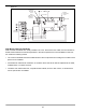
Figure 12-1 24 VAC Drain Valve A Steam Generator A High Water Switch A Low-Voltage Low-Energy Controls Panel Switches Mode Tank Drain Select On/Off On/Off 24 VAC Fill Valve Main Control Humidistat Micro Controller Printed Circuit Board High Limit* Humidistat Current Transformer Air Flow* Switch 24 VAC Contactor N.O.
INSTRUMENT PANEL MODE BUTTON, INDICATOR, and DISPLAY DEMAND CURRENT % POWER DIAGNOSTIC FILL DRAIN HIGH WATER TANK OFF MODE SELECT The Mode select button is depressed for approximately ½ second to switch both the "display mode selected" indicator and the 3 digit display between: -DEMAND- % of humidistat control range. -CURRENT- actual current in amps. -% POWER- ratio of current draw to the nominal rating of the unit. -DIAGNOSTIC MODE- readout of diagnostic codes.
START-UP PROCEDURE FOR ARMSTRONG SERIES EHU-700 HUMIDIFIERS The following steps should be performed on all newly installed Series EHU-700 Humidifiers to ensure that the humidifier and the entire humidification system functions correctly. BEFORE TURNING ON THE POWER Figure 14-1 1) Examine the wiring and the components in the electrical compartment. 2) Check for any loose wires or quickconnect terminals that may have been pulled loose.
If the stat demand display is greater than 35% and the unit does not begin filling, press the mode select button three times and the diagnostic mode indicator will light. Note the diagnostic message and refer to the diagnostics information in the troubleshooting section of this manual (page 20). c) If the stat demand is less than 35%, force a 100% humidity demand by setting humidistat dial to 95% RH.
15) Verify that all of the input/output circuits are functioning properly by entering the input/output diagnostics mode. Press the mode button until the diagnostics indicator lights and wait ten seconds. The unit will do a complete self-diagnostic check. See CO in the diagnostics section of this manual (page 20) for more information. 16) Turn power off, if humidification is not needed. 17) Close and lock the doors, and store the key away from the unit.
TROUBLESHOOTING GUIDE CAUTION!: Disconnect the electric power supply at the circuit breaker or switch whenever the unit is to be inspected or serviced. DO NOT USE THE TANK ON/OFF SWITCH ON THE HUMIDIFIER BECAUSE THIS SWITCH DISCONNECTS THE STEAM GENERATOR TANK ONLY. PRINCIPLE OF OPERATION - AN OVERVIEW The Armstrong Series EHU-700 electronic steam humidifier converts ordinary tap water to steam and distributes it within the air being humidified to bring the relative humidity up to the desired level.
A high-water float switch prevents water carry-over into the duct due to an excessive water level in the tank. When the high water limit is reached the HIGH WATER light comes on and the fill valve is blocked until some water is boiled away and the water level drops. This is common during startup. If the high water light comes on and the water level is in the lower half of the steam generator, contact the factory for assistance. This is due to high static pressure.
Monitoring Current: While the unit is filling, the current should increase. As the current approaches the maximum rating of the unit, it increases more slowly, especially in higher capacity units. With the tank on, and the fill and drain circuits idle, the current should fall slowly. When the unit is draining, the current should decrease at a moderate rate. Monitoring % Power: The percentage power equates to the percentage of maximum steam output.
EHU-700 DIAGNOSTICS THE Series EHU-700 has built in diagnostics to detect system problems early, before they become severe. If possible, the diagnostic routine performs corrective measures. If necessary, the unit is shutdown and a dry contact is closed to enable a remote alarm. The diagnostic messages that result in the unit being shutdown are displayed automatically. The other messages are displayed when the diagnostic display mode is selected with the mode switch.
C04: HIGH LIMIT CIRCUIT: When the humidity in the duct reaches the high limit stat set-point, the circuit will open and the microcontroller will de-energize the contactor. The diagnostic mode will display the message C04 and the fill solenoid is blocked. C05: DRAIN SYSTEM FAILURE: This routine checks for a failure to reduce current if the drain valve is energized for more than five seconds.
C09: I/O DIAGNOSTICS If the display mode selection is left in the diagnostic mode for 10 seconds, the Input/Output circuit diagnostic check will begin. The display will show the message C09, the tank will be off, and the diagnostics mode light will remain on. Output Circuits: The diagnostics will first check all the output circuits: fill valve, drain valve, and tank contactor to make sure they are working.
WATER QUALITY AND TREATMENT FOR EHU SERIES HUMIDIFIERS GENERAL Series EHU 700 electronic humidifiers use ordinary tap water in their operation. The quality of this water affects both the operation and the maintenance of the humidifier. How the EHU works: The EHU is an electrode boiler. When no water is present, the electrodes are separated by air, an insulator, so no current flows. When tap water contacts the electrodes it conducts current between the electrodes, heating the water.
Results: -Excessive time needed to reach set point during star-up. -Poor humidity control. Remedy: -Add 1/2 teaspoon of Epsom salts to the fill cup. After start-up the automatic drain program should maintain the unit at full capacity. -If problem persists, contact the factory. WHEN WATER CONDUCTIVITY IS TOO HIGH Indicators: -Water level just touching tip of electrodes. -Arcing and foaming in the tank. -Frequent drain cycles (every time the fill valve opens) that last up to 10 seconds.
EHU-701, -703, -704 Series Electronic Steam Humidifier Repair Parts Steam Generators Complete Item Part No.
Valves and Mechanical Parts Item Part No.
Electrical Parts Item Part No.
Figure 28-1. EHU-700 Parts List 23 40 47 29 49 56 48 54 16 53 25 46 62 30 55 31 50 32 18 52 19 51 33 61 57 15 22 20 21 42 17 Figure 28-2.
MAINTENANCE RECOMMENDED MAINTENANCE SCHEDULE 1 TO 2 DAYS AFTER START UP 1) 2) 3) 4) 5) Check unit operation. Look in drain pan for leaks. Check steam piping for leaks. Observe duct low points for signs of poor humidity distribution. Be sure unit is draining freely by pushing the manual drain button (the manual tank off button should not be depressed). 1 MONTH TO 1 YEAR 1) Repeat the 5 steps outlined above. 2) Clean, repair, or replace steam generator.
If the electrodes begin to disintegrate, the tank may turn black or red, and arcing or flashing may be visible inside the tank while it is operating. IF YOU NOTICE EXCESSIVE ARCING, SHUT THE UNIT OFF AND CALL THE FACTORY BEFORE RE-STARTING UNIT. To replace the electrodes, please refer to the "Tank Disassembly and Electrode Replacement" Section of this manual.
STEAM GENERATOR CHEMICAL CLEANING PROCEDURE This procedure is intended as a guide only for the chemical cleaning of the generator in all EHU models. Read and follow label directions on any cleaning product. Check local codes before disposing of chemicals. Caution: Muriatic acid can cause severe chemical burns if not handled properly. Wear rubber gloves and eye protection when using. Read and follow carefully the safety procedures on the package. 1) Obtain several gallons of muriatic acid.
12) Reassemble tank. Make sure o-rings are still on electrode terminals. Also check condition of steam generator o-ring. After a couple cleanings, it will need to be replaced. Make sure o-ring is sealed in its groove and not pinched when halves are put together. Do not over-tighten nuts that hold electrodes in place. This is an o-ring seal so nuts should be "snug". 13) Re-install the steam generator tank. Check out for proper operation.
TANK DISASSEMBLY, CLEANING, AND ELECTRODE REPLACEMENT MODELS EHU-703 AND 704, SINGLE AND THREE PHASE 1) Using a 7/16" wrench, disconnect the jumper wires from the steam generator. 2) Remove 24 metal clips by pushing gently on top of each clip with a screwdriver while cupping the clip with the other hand. 3) Lift the top half of the tank free of the bottom half and rest it on the electrodes. Use a ¾" wrench to loosen and remove the nuts from the six electrode studs.
MODEL EHU-701, SINGLE AND THREE PHASE Figure 35-1 1) Remove 24 metal clips by pushing gently on top of each clip with a screwdriver while cupping the clip with the other hand. Barrier 2) Clean the inside of the steam generator thoroughly unsing a scraper, stiff bristle brush and/or water spray and rinse with clear water. Barrier Retainer 3) High voltage units are supplied with a barrier/drain screen assembly in the lower tank half to increase tank life.
b) While the tank is out, look into the lower end of the tank. Make sure the drain screen is in place. Also check for accumulations of lime at the bottom of the tank. Refer to "Steam Generator Disassembly" and "Cleaning Procedure" sections to rectify these problems. 3) If the tank drains well when the water level is high but poorly or not at all when it is low, check the duct pressure where the dispersion tube is mounted. A negative duct pressure can cause drainage problems.
HUMIDISTAT DATA AUTOCAL PROCEDURE 1. Measure the room humidity near the humidistat with an accurate hygrometer. 2. Turn the humidistat set point dial to match the reading of the hygrometer. 3. Push and hold the Autocal button for more than 3 seconds or until the internal red light turns On and Off. SENSOR FAILURE PROTECTION The sensor is the most sensitive part of the humidistat and also the most exposed.
DIMENSIONS Figure 37-1. Dimension drawing. Duct Humidistat Security Screw Wiring From Back Wiring From Top 1-5/8" (41 mm) "Autocal" Button (Invisible) 1" (25 mm) 3-1/4" (83 mm) 4-1/2" (114 mm) Base 1-1/4" (32 mm) Cover 2-7/8" (71 mm) 2" (50 mm) 1-1/4" (32 mm) 3-3/4" (96 mm) 2-7/8" (71 mm) 15/16" (23 mm) Cover Note: Specifications and equipment are subject to change without prior notice.
AIR SUPPLY HIGH LIMIT HUMIDITY SENSOR Table 4: Example showing proportional high limit override signal in supply duct. Control Output Level The A 17898 (H270) includes a high limit circuit. This allows the use of a second humidity in the supply air. Input signal goes to terminals #8 on the humidistat. High limit set point is preprogrammed at 85%. It can be readjusted using the A19517 service tool.
APPLICATION EXAMPLE Steam humidification system controlled by a 0 to 10 Vdc valve wired to output #1. Remote humidity display using 0 to 5 Vdc signal is wired to output #2. The humidity sensor is located in the return air duct. A proportional high limit humidity sensor is installed in the supply duct. An outdoor temperature sensor is installed in the fresh air duct. Humidistat model number: H270-69-13-10-31 figure 42-1.
Dimensional Information I H H Q Conn. for Dispersion 1-1/2" ID Hose Conn.