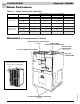
Service Reference Manual HWC Thru-the-Wall Units Models: HWC Premier 122, 182, 242, 302 123, 183, 243, 303
Copyright © 1998 Armstrong Air Conditioning Inc. All rights reserved. Disclaimer This manual presents information and guidelines for proper installation, adjustment, operation and maintenance of Armstrong Magic-Pak HW/HWC Thru-the-Wall units. Read this manual before attempting assembly, installation, start-up, adjustment or operation of the unit. If you have any questions about the operation of the unit or a particular safety device, call or write Armstrong Air Conditioning Inc.
Service Reference Manual TABLE OF CONTENTS TABLE OF CONTENTS 1 - Specifications 2 - Sequence of Operations 3 - Unit Tear Down 4 - Component Location Illustrations 5 - Unit Components 6 - Installation 7 - Accessories 8 - Parts Lists SRM-HW/HWC 8/99 9 - Troubleshooting/Performance/ Charge Weights Go to: If you need information on: Section 1 Performance, electrical data and cabinet dimensions. Section 2 Sequence of operation descriptions with accompanying schematics.
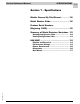
Service Reference Manual SPECIFICATIONS 1-1 Section 1 - Specifications Models Covered By This Manual ............ 1-2 Model Number Guide ............................ 1-2 Product Serial Numbers (Beginning 1993) ................................. 1-2 Summary of Model Revisions/Variations 1-3 Heating Configuration Table ........................ 1-3 Cooling Configuration Table ......................... 1-3 HW/HWC ............................................ 1-4 SRM-HW/HWC 8/99 Physical and Electrical ......
SPECIFICATIONS Magic-Pak: HW/HWC 1-2 Models Covered By This Manual HWC Gas Heating/Electric Cooling Units HW122, 123 HW182,183 HW242, 243 HW302, 303 HW Gas Heating Only Units 26HW 38HW 51HW 64HW Model Number Guide HW/HWC Models 26 H W C 12 2 -- 2A 26 = Rated Input BTU/Hr x 1000 H = Gas Heat W = Thru-the-Wall C = Cooling 12 = Nominal Cooling BTU/Hr x 1000 2 = Cooling Efficiency 2 - 9.
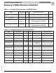
Service Reference Manual SPECIFICATIONS 1-3 Summary of Model Revisions/Variations Table 1-1 Heating Configurations of HW/HWC Units Model Configuration AFUE Ignition/Blower Control Ignition Type (All) HWC (123, 183, 243, 303) -1 Gas Heat/ Electric Cool 80 UTech Combination Ignition/Blower Control 1097 DSI (All) HW -9 Gas Heat Only 80 UTech Combination Ignition/Blower Control 1097 DSI (All) HWC (122, 182, 242, 302) -11, -10, -9, -8, -7, -6, -5 Gas Heat/ Electric Cool 80 Ignition Control: Fe
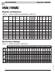
SPECIFICATIONS Magic-Pak: HW/HWC 1-4 HW/HWC Physical and Electrical Table 1-3 Physical and Electrical Specifications - HWC Units Model Voltage/ Hz/Phase Normal Voltage Range Min. Circuit Ampacity Max. Fuse/HACR Brkr. (amps) Comp. Rated Load (amps) Comp. Locked Rotor (amps) O.D. Fan Dia. (in.) Nom. RPM Outside Fan Rated Load (amps) Rated HP Indoor Wheel dia. x width (in.) Blower Rated HP Refrig. Charge (oz.) Weight (lbs.) 26HWC122/123 208-230/60/1 197-253 8.3 15 5.0 26.
Service Reference Manual SPECIFICATIONS 1-5 Performance Ratings (continued) Table 1-5 Performance Ratings - HWC182/183 Outdoor Air Temperature Entering Outdoor Coil 95° 85° Enter. Wet Bulb 63° 67° 71° Total Air Vol. (CFM) Total Cooling Capacity (Btuh) 550 18400 Comp. Watts Input S/T at 75° Dry Bulb S/T at 80° Dry Bulb S/T at 85° Dry Bulb Total Cooling Capacity (Btuh) 1370 .75 .90 1.00 17100 105° Comp.
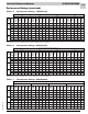
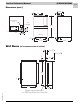
SPECIFICATIONS Magic-Pak: HW/HWC 1-6 Blower Performance Table 1-8 Blower Performance - HWC Units CFM @ ext. static pressure - in. w.c. with filter(s) Blower Speed Model HWC122/123 HWC182,242,302 HWC183,243,303 Dimensions 0.2 0.3 0.4 0.
Service Reference Manual SPECIFICATIONS 1-7 Dimensions (cont.
Service Reference Manual SEQUENCE OF OPERATIONS 2-1 Section 2 - Sequence of Operation HWC123,183,243,303 ........................ 2-4 Simplified Sequence ........................................ 2-5 Detailed Sequence .......................................... 2-6 POWER ...................................................................... 2-6 CALL FOR HEAT ........................................................ 2-6 LIMIT/ROLLOUT OPENS ...........................................
SPECIFICATIONS Magic-Pak: HW/HWC 2-2 HWC122,182,242,302 (w/Fenwal 05-29 Ignition Control) ....... 2-26 Simplified Sequence ...................................... 2-27 Detailed Sequence ........................................ 2-28 POWER .................................................................... 2-28 CALL FOR HEAT ...................................................... 2-28 FLAME SENSE ......................................................... 2-29 LIMIT OPENS .....................................
Service Reference Manual SEQUENCE OF OPERATIONS 2-3 SRM-HW/HWC 2/99 BLANK PAGE
SPECIFICATIONS Magic-Pak: HW/HWC 2-4 HWC123, 183, 243, 303 (w/United Technologies 1097 Spark Ignition System) CONNECTION DIAGRAM CIRCUITS ENERGIZED } COPPER CONDUCTORS 208/230-1-60 ONLY POWER SUPPLY OPERATING MODE HEATING COOLING FAN YELLOW RED CIRCUIT R-W R-G-Y R-G BLUE LINE VOLTAGE-FACTORY LINE VOLTAGE-FACTORY WHEN USED LINE VOLTAGE-FIELD LOW VOLTAGE-FACTORY LOW VOLTAGE-FIELD BLACK 4 5 VIOLET WHT IGNITION CONTROL PRESSURE SWITCH 4 5 6 RED ELECTRODE GND R R G G Y Y W W GREEN O
Service Reference Manual SEQUENCE OF OPERATIONS 2-5 Simplified Sequence - HWC123,183, 243, 303 Refer to Figure 2-1 • 208/230V power is supplied to the junction box on top of the unit • 24V power is supplied from the unit transformer to the thermostat CALL FOR HEAT 1. The thermostat closes the R-W circuit, sending a 24-volt signal to the unit. 2. The 24-volt signal energizes the combustion blower, causing the pressure switch to close. 3.
SPECIFICATIONS Magic-Pak: HW/HWC 2-6 Detailed Sequence - HWC123, 183, 243, 303 Refer to Figure 2-1 POWER Line Voltage With the unit at rest (no call from the thermostat), line voltage will be present: L1 Power 1. Through the L1 black lead to the L1 terminal on the ignition control 2. At the L1 contactor terminal 3. At the transformer terminal marked 208-240V L2 Power 1. Through the L2 black lead to the induced draft blower 2. At the L2 contactor terminal 3. A transformer common terminal 4.
Service Reference Manual SEQUENCE OF OPERATIONS 2-7 9. After 30-second “on” delay, the circulating air blower relay energizes the heat terminal and the circulating air blower is energized. 10. The unit will continue to operate normally until the R-W circuit is interrupted. 11. When the heat call is satisfied, the thermostat will interrupt the R-W circuit. This causes the 24-volt signal to the white wire in the unit to be de-energized. 12.
SPECIFICATIONS Magic-Pak: HW/HWC 2-8 8. The 24-volt signal will only be supplied to the limit switch circuit through pin 6 of the 6-pin ignition wire harness and to the pressure switch circuit through pin 2 of the 6-pin ignition wire harness. 9. The system will repeat this sequence until the pressure switch closes and the 24-volt signal is restored at pin 5 of the 6-pin ignition wire harness.
Service Reference Manual SEQUENCE OF OPERATIONS 2-9 6. After the 90-second delay, the ignition control deenergizes the cooling speed relay and the circulating air blower stops. FAN ON 1. When the thermostat is switched to the “FAN ON” position, the R-G circuit sends a 24-volt signal to pin 4 of the 5-pin thermostat harness. 2. The 24-volt signal energizes the cooling speed relay, sending L1 power to the ACB COOL terminal of the ignition control. 3.
SPECIFICATIONS Magic-Pak: HW/HWC 2-10 HW (Heating Only) (w/United Technologies 1097 Spark Ignition System) CONNECTION DIAGRAM } 208/230-1-60 POWER SUPPLY COPPER CONDUCTORS ONLY CIRCUITS ENERGIZED WIRE NUT OPERATING MODE HEATING COOLING FAN YELLOW RED LINE VOLTAGE-FACTORY LINE VOLTAGE-FACTORY WHEN USED LINE VOLTAGE-FIELD LOW VOLTAGE-FACTORY LOW VOLTAGE-FIELD BLUE BLACK GND ORANGE R R G G Y W W Y } THERMOSTAT FLAME ROD NOTE: IF ANY OF THE ORIGINAL WIRES ARE REPLACED, THE SAME SIZE AN
Service Reference Manual SEQUENCE OF OPERATIONS 2-11 Simplified Sequence - HW (w/UTEC 1097 Board) Refer to Figure 2-2 CALL FOR HEAT 1. The indoor thermostat energizes the R-W circuit, sending a 24-volt signal to the ignition control. 2. The 24-volt signal causes the induced draft blower to start, which closes the pressure switch. 3. Once the pressure switch closes, a 30-second induced draft blower pre-purge starts. 4.
SPECIFICATIONS Magic-Pak: HW/HWC 2-12 Detailed Sequence - HW (w/UTEC 1097 Board) Refer to Figure 2-2 POWER Line Voltage With the unit at rest (no call from the thermostat), line voltage will be present: L1 Power 1. Through the L1 black lead to the L1 terminal on the ignition control 2. At the transformer terminal marked 208-240V L2 Power 1. Through the L2 black lead to the induced draft blower 2. Transformer common terminal 3.
Service Reference Manual SEQUENCE OF OPERATIONS 2-13 12. The gas valve closes immediately as 24V through pin 4 of the 6-pin ignition wire harness is deenergized by the ignition control. 13. The ignition control initiates a 120-second circulating air blower “off” delay and 5-second combustion blower post-purge delay. 14. After 5 seconds, the combustion blower shuts off. 15. After 120 seconds, the circulating air blower shuts off and the system returns to standby mode. 9.
SPECIFICATIONS Magic-Pak: HW/HWC 2-14 FAILED FLAME SENSE/TRIAL FOR IGNITION When the pressure switch closes and a 24-volt signal is sent to pin 5 of the 6-pin ignition wire harness, the spark ignition cable terminal and pin 4 of the 6-pin ignition wire harness energize. 1. As spark voltage is supplied to the ignitor electrodes, the gas valve opens and this causes the burners to ignite. 2.
Service Reference Manual SEQUENCE OF OPERATIONS 2-15 SRM-HW/HWC 2/99 BLANK PAGE
SPECIFICATIONS Magic-Pak: HW/HWC 2-16 HWC122, 182, 242, 302 (w/Fenwal T riton 2461D DSI Ignition Contr ol) Triton Control) CIRCUITS ENERGIZED OPERATING MODE 208/230-1-60 COPPER CONDUCTORS POWER SUPPLY ONLY BLACK BLACK BLUE BLUE LIMIT SWITCH C NC WHITE GAS VALVE V2 IGNITION CONTROL GND PRESSURE SWITCH WHITE R R W W Y G Y G THERMOSTAT BROWN BLACK BLACK GREEN WHITE RED YELLOW BLUE COMBUSTION BLOWER BLACK BLACK RED GREEN ELECTRODE CABLE WHITE ORN ORN NO MANUAL RESET WHITE LIN
Service Reference Manual SEQUENCE OF OPERATIONS 2-17 Simplified Sequence - HWC122,182, 242, 302 (w/Fenwal Triton 2461D DSI Ignition Control) SRM-HW/HWC 2/99 Refer to Figure 2-3 CALL FOR HEAT CALL FOR COOLING 1. A call for heat closes the circuit between wires R (red) and W (white) on the unit’s thermostat connections. 2. A low voltage (24 volts) signal is sent to the ignition control, closing a relay which sends line voltage to the induced draft blower.
SPECIFICATIONS Magic-Pak: HW/HWC 2-18 Detailed Sequence - HWC122, 182, 242, 302 (w/Fenwal Triton 2461D DSI Ignition Control) Refer to Figure 2-3 POWER Line Voltage When the service disconnect switch is closed, power is sent to the unit (unit in standby, no signal from the thermostat). Power (208 - 230 volts A/C) is supplied to both black wires located in the junction block on top of the unit. Line voltage will be present at the following locations: First black wire 1. L-1 on the ignition control 2.
Service Reference Manual SEQUENCE OF OPERATIONS 2-19 LIMIT OPENS If the limit switch opens for any reason during a call for heat, the following happens: 1. If the limit switch senses that the temperature in the unit is too high, the contacts between terminals C and NC on the limit switch open and the contacts between C and NO close. This interrupts the 24-volt signal to the pressure switch and also deenergizes terminal P.SW on the ignition control.
SPECIFICATIONS Magic-Pak: HW/HWC 2-20 5. The circulating air blower shuts off approximately 90 seconds after G terminal on the blower control board is de-energized (see note below). FAN ON Low Voltage 1. When the switch on the thermostat is moved to the “FAN ON” position, a 24-volt signal is sent to G. 2. With G energized, the blower control board starts a countdown to fan “on”. After approximately 15 seconds, the fan starts (see note below). 3.
Service Reference Manual SEQUENCE OF OPERATIONS 2-21 SRM-HW/HWC 2/99 BLANK PAGE
SPECIFICATIONS Magic-Pak: HW/HWC 2-22 HW (Heating Only) (w/Fenwal Triton 2461D DSI Ignition Control) CIRCUITS ENERGIZED OPERATING MODE 208/230-1-60 COPPER CONDUCTORS POWER SUPPLY ONLY PINK BROWN WHITE ORANGE BLUE BLUE V2 GND BLACK BLACK PRESSURE SWITCH LIMIT SWITCH R R W Y G W Y GREEN WHITE RED YELLOW BLUE RED GREEN ELECTRODE CABLE GAS VALVE NO NC WHITE ORANGE WHITE BLACK BLACK TH P.
Service Reference Manual SEQUENCE OF OPERATIONS 2-23 Simplified Sequence - HW (w/Fenwal 2461D Board) Refer to Figure 2-4 CALL FOR HEAT SRM-HW/HWC 2/99 1. A call for heat closes the circuit between R and W on the thermostat. This sends a 24-volt signal to the white wire on the unit. 2. The 24-volt signal energizes terminal TH on the ignition control and the W terminal on the blower control board. 3. With the TH terminal energized, the ignition control closes an internal relay.
SPECIFICATIONS Magic-Pak: HW/HWC 2-24 Detailed Sequence - HW (w/Fenwal Triton 2461D Ignition Control) Refer to Figure 2-4 POWER Line Voltage When the service disconnect switch is closed, power is sent to the unit (unit in standby, no signal from thermostat). Power (208 - 230 volts A/C) is supplied to the two black wires located in the junction block on top of the unit. Line voltage will be present at the following locations: First black wire 1. L-1 on the ignition control 2.
Service Reference Manual SEQUENCE OF OPERATIONS 2-25 9. When W de-energizes, the gas valve immediately shuts down and the induced draft blower also stops after several seconds. 10. The blower control board starts a countdown to blower “off”. Approximately 90 seconds later, the circulating air blower shuts down. Note: If the P.SW and TH terminals energize at the same time, the ignition control will not respond. A pressure switch being stuck closed is an example of what would cause this to happen.
SPECIFICATIONS Magic-Pak: HW/HWC 2-26 HWC122, 182, 242, 302 (w/Fenwal 05-29 Ignition Contr ol) Control) CIRCUITS ENERGIZED OPERATING MODE 208/230-1-60 COPPER CONDUCTORS POWER SUPPLY ONLY WHITE LIMIT SWITCH C NC WHITE WHITE FLAME SENSOR WHITE NO MANUAL RESET PRESSURE SWITCH LINE VOLTAGE - FACTORY LINE VOLTAGE - FACTORY (WHEN USED) LINE VOLTAGE - FIELD LOW VOLTAGE - FACTORY LOW VOLTAGE - FIELD RED BLUE BLUE BLACK BLACK V1 P.
Service Reference Manual SEQUENCE OF OPERATIONS 2-27 Simplified Sequence - HWC122, 182, 242, 302 (w/Fenwal 05-29 Ignition Control) Refer to Figure 2-5 CALL FOR HEAT CALL FOR COOLING 1. The thermostat energizes the R-W circuit, sending a 24-volt signal to the W wire at the unit. 2. The 24-volt signal is sent to the ignition control, closing the combustion blower relay and causing the combustion blower to run. 3.
SPECIFICATIONS Magic-Pak: HW/HWC 2-28 Detailed Sequence - HWC122, 182, 242, 302 (w/Fenwal 05-29 Ignition Control) Refer to Figure 2-5 POWER Line Voltage When the service disconnect switch is closed, power is sent to the unit (unit in standby, no signal from the thermostat). Power (208 - 230 volts A/C) is supplied to both black wires located in the junction block on top of the unit. Line voltage will be present at the following locations: First black wire 1. L-1 on the ignition module 2.
Service Reference Manual SEQUENCE OF OPERATIONS 2-29 9. With W de-energized, the gas valve closes immediately and the induced draft blower stops several seconds later. 10. The blower control board starts a 90-second circulating air blower “off” delay. Approximately 90 seconds later, the blower stops. FLAME SENSE 1. During a call for heat, the spark terminal is energized and the gas valve is opened to light the burners. 2.
SPECIFICATIONS Magic-Pak: HW/HWC 2-30 3. The unit continues cooling as long as both Y and G are energized. When the cooling call is satisfied, the circuit between Y, G and R is interrupted. The contactor immediately opens, interrupting power to the compressor and the outdoor cooling fan. 4. With the low voltage signal to terminal G on the blower control board interrupted, the board starts a countdown to blower “off”.
Service Reference Manual SEQUENCE OF OPERATIONS 2-31 SRM-HW/HWC 2/99 BLANK PAGE
SPECIFICATIONS Magic-Pak: HW/HWC 2-32 HW (Heating Only) (w/Fenwal 05-29 Ignition Control) CIRCUITS ENERGIZED OPERATING MODE BROWN MANUAL RESET WHITE WHITE FLAME NO LIMIT SWITCH NC PRESSURE SWITCH WHITE WHITE SENSOR C LINE VOLTAGE - FACTORY LINE VOLTAGE - FACTORY (WHEN USED) LINE VOLTAGE - FIELD LOW VOLTAGE - FACTORY LOW VOLTAGE - FACTORY (WHEN USED) LOW VOLTAGE - FIELD WHITE RED BLUE BLUE ORANGE ORANGE BLACK BLACK V1 P.
Service Reference Manual SEQUENCE OF OPERATIONS 2-33 Simplified Sequence - HW (w/Fenwal 05-29 Board) Refer to Figure 2-6 CALL FOR HEAT SRM-HW/HWC 2/99 1. The indoor thermostat calls for heat by energizing the R-W circuit. 2. This sends a 24-volt signal to the ignition control, causing the induced draft blower to run. 3. A 24-volt signal is also sent to the blower control board at this time, starting a 60-second circulating air blower “on” delay.
SPECIFICATIONS Magic-Pak: HW/HWC 2-34 Detailed Sequence - HW (w/Fenwal 05-29 Ignition Control) Refer to Figure 2-6 POWER Line Voltage When the service disconnect switch is closed, power is sent to the unit (unit in standby, no signal from the thermostat). Power (208 - 230 volts A/C) is supplied to both black wires located in the junction block on top of the unit. Line voltage will be present at the following locations: First black wire 1. L-1 on the ignition module 2.
Service Reference Manual SEQUENCE OF OPERATIONS 2-35 8. When the call for heat is satisfied, the circuit between R and W is interrupted, de-energizing W. 9. With W de-energized, the gas valve closes immediately and the induced draft blower stops several seconds later. 10. The blower control board starts a 90-second blower “off” delay. Approximately 90 seconds later, the blower stops. FLAME SENSE 1. During a call for heat, the spark terminal is energized and the gas valve is opened to light the burners.
SPECIFICATIONS Magic-Pak: HW/HWC 2-36 HWC123, 183, 243, 303 Low Ambient (w/United Technologies 1097 Spark Ignition System) CONNECTION DIAGRAM CIRCUITS ENERGIZED 208/230-1-60 COPPER CONDUCTORS POWER SUPPLY ONLY OPERATING MODE HEATING COOLING FAN } YELLOW RED BLUE BLACK COOL BLACK (WHEN USED) WHITE IGNITION CONTROL 4 5 6 1 2 3 RED LINE VOLTAGE-FACTORY LINE VOLTAGE-FACTORY WHEN USED LINE VOLTAGE-FIELD LOW VOLTAGE-FACTORY LOW VOLTAGE-FIELD ELECTRODE GND 24VAC Y C W G R PRESSURE SWITCH BLACK
Service Reference Manual SEQUENCE OF OPERATIONS 2-37 HWC123,183, 243, 303 Low Ambient Model Refer to Figure 2-7 The low ambient switch is designed to allow the operation of the air conditioning unit below the normal operating range. On units equipped with this switch, sequence of operation during a cooling call is modified when outdoor temperatures fall below the normal operating range.
SPECIFICATIONS Magic-Pak: HW/HWC 2-38 HWC122, 182, 242, 302 Low Ambient CIRCUITS ENERGIZED OPERATING MODE WHITE PRESSURE SWITCH C WHITE R R W Y G W THERMOSTAT Y G BROWN COMBUSTION BLOWER BLACK BLACK NOTE: IF ANY OF THE ORIGINAL WIRES ARE REPLACED, THE SAME SIZE AND TYPE WIRE MUST BE USED. GREEN WHITE RED YELLOW BLUE GREEN RED BLACK BLACK BLUE BLUE V2 GND ELECTRODE CABLE GAS VALVE NC RED WHITE ORN ORN NO MANUAL RESET WHITE TH P.
Service Reference Manual SEQUENCE OF OPERATIONS 2-39 HWC122,182, 242, 302 Low Ambient Model Refer to Figure 2-8 The low ambient switch is designed to allow the operation of the air conditioning unit below the normal operating range. On units equipped with this switch, sequence of operation during a cooling call is modified when outdoor temperatures fall below the normal operating range.
Service Reference Manual UNIT TEAR DOWN 3-1 Section 3 - Unit Tear Down Heating Section Heat Exchanger Removal ............................ 3-2 Induced Draft Blower Removal ..................... 3-2 Cooling Section SRM-HW/HWC 8/99 Chassis Removal ........................................ 3-4 Evaporator Blower Assembly Removal ..........
UNIT TEAR DOWN Magic-Pak: HW/HWC 3-2 UNIT TEAR DOWN HWC units are comprised of two major sections. The heating section is located in the top half of the unit. It contains the heat exchanger and the majority of the components associated with the heating function: controls, burners, switches, etc.... The total heating section is not removable as a complete unit. The heat exchanger may be removed separately for service (see below). The cooling section is located in the lower half of the unit.
Service Reference Manual UNIT TEAR DOWN 3-3 PLATE MOUNTING SCREWS INDUCED DRAFT BLOWER/ COMBUSTION BLOWER HEAT EXCHANGER FRONT HEAT SECTION PANEL GAS VALVE HEATING SECTION VESTIBULE PANEL CONTROL SECTION BURNER TRAY COOLING SECTION BURNER ACCESS PANEL FILTER ACCESS DOOR SRM-HW/HWC 8/99 Figure 3-1
UNIT TEAR DOWN Magic-Pak: HW/HWC 3-4 Cooling Section Chassis Removal: The cooling chassis may be removed from behind the filter access door. Refer to the following directions and Figures 3-1 to 3-4. To remove the cooling chassis: 1. 2. 3. 4. 5. 6. 7. 8. 9. 10. Disconnect all power to the unit. Shut off and disconnect the gas supply. Remove the filter access door (Figure 3-1). Disconnect L1 and L2 from the compressor contactor (Figure 3-2). Disconnect the 6-pin low voltage molex plug (Figure 3-2).
Service Reference Manual UNIT TEAR DOWN 3-5 EVAPORATOR BLOWER MOTOR Figure 3-3 EVAPORATOR COMPRESSOR EVAPORATOR DRAIN TUBE CONNECTION EVAPORATOR DRAIN PAN CHASSIS SHOWN PARTIALLY REMOVED LOW VOLTAGE MOLEX PLUG Figure 3-4 SRM-HW/HWC 8/99 EVAPORATOR DRAIN TUBE CONNECTION PERMAGUM SEAL DRAIN HOSE (NOT PICTURED) ARMSTRONG P/N 03613A001 17" LONG .63" (5/8") I.D. .
UNIT TEAR DOWN Magic-Pak: HW/HWC 3-6 Evaporator Blower Assembly Removal: The evaporator blower assembly is removable as one complete section. To remove the assembly, the chassis must be removed first (see page 34). Refer to the following directions and Figure 3-5. To remove the evaporator blower assembly: 1. 2. 3. 4. 5. Remove the four mounting screws from the blower assembly. Remove the four control panel screws. Slide control panel toward yourself about 1".
Service Reference Manual COMPONENT LOCATION ILLUSTRATIONS 4-1 Section 4 - Component Location Illustrations HW/HWC(3) Unit ................................. 4-2 HW/HWC(2) Unit ................................. 4-3 HW/HWC - Panels................................ 4-4 HW/HWC - Exterior Louver/Grill Panel .. 4-5 HWC Chassis Assembly ........................ 4-6 HWC Chassis Assembly - Top View .........
COMPONENT LOCATION ILLUSTRATIONS Magic-Pak: HW/HWC 4-2 HW/HWC123,183,243,303 IGNITION/BLOWER CONTROL BOARD (*24) UNITED TECHNOLOGIES 1097-83-400A/1097-400-I (DSI)* ARMSTRONG P/N 44990-001 MAIN LIMIT SWITCH (*52) ARMSTRONG P/N 40154B007 GAS VALVE HONEYWELL VR8105M8202 ARMSTRONG P/N 44987-001 HEATING SECTION CONTROL SECTION PRESSURE SWITCH (*57) COOLING SECTION BURNER TRAY * SEE COMPONENT SECTION FOR FURTHER DETAIL OF IGNITION/BLOWER CONTROL FIGURE 4-1 The numbers in parentheses in the drawing a
Service Reference Manual COMPONENT LOCATION ILLUSTRATIONS 4-3 HW/HWC122, 182, 242, 302 FENWAL IGNITION CONTROL - 2 MODELS (*24) FENWAL TRITON 2461D 900-227 - ARMSTRONG P/N 43110-002 FENWAL 05-29 - ARMSTRONG P/N 39048B001 (SEE NOTE BELOW) MAIN LIMIT SWITCH (*52) FLUE BOX INDUCED DRAFT BLOWER/ COMBUSTION BLOWER (*63) ARMSTRONG P/N 41144-001 GAS VALVE (*7) WHITE RODGERS 25K49-120 ARMSTRONG P/N 43108-001 COMBUSTION AIR INLET (5") HEATING SECTION BURNER COVER BURNER TRAY ASSEMBLY BECKETT BURNER MODELS: TL10
COMPONENT LOCATION ILLUSTRATIONS Magic-Pak: HW/HWC 4-4 HW/HWC - Panels HEAT EXCHANGER ACCESS PANEL ARMSTRONG P/N 38782D001 TOP PANEL ASSEMBLY ARMSTRONG P/N 03455D007 INSPECTION WINDOW ARMSTRONG P/N 38092A002 SIDE PANEL ARMSTRONG P/N 38769D001 UPPER LOUVER PANEL ARMSTRONG P/N 03545C000 LOWER GRILL PANEL ARMSTRONG P/N 03551D100 COOLING CONTROL ACCESS PANEL ARMSTRONG P/N 03938C004 HEATING COMPARTMENT DOOR ARMSTRONG P/N 38987B004 DOOR HANDLE ARMSTRONG P/N 37701B001 SIDE PANEL ARMSTRONG P/N 38769D002
Service Reference Manual COMPONENT LOCATION ILLUSTRATIONS 4-5 HW/HWC Exterior Louver/Grill Panel SIDE VIEW CONDENSER AIR FLOW OUTLET EXTERIOR UPPER LOUVER PANEL ARMSTRONG P/N 03545C000 LOUVERS POINT UPWARD AT 45° ANGLE EXTERIOR LOWER GRILL PANEL ARMSTRONG P/N 03551D100 CONDENSER AIR FLOW INLET GRILL IS FLAT WITH RECTANGULAR OPENINGS FIGURE 4-4 SRM-HW/HWC 2/99 Note: Panels found in the drawing above are not listed in the Parts List section that begins on page 8-1.
COMPONENT LOCATION ILLUSTRATIONS Magic-Pak: HW/HWC 4-6 HWC Chassis Assembly EVAPORATOR BLOWER MOTOR (*69) COMPRESSOR CAPACITOR (*271) COMPRESSOR CONTACTOR (*278) ARMSTRONG P/N 03575C001 CONDENSING FAN SHROUD CONDENSING FAN CAPACITOR (*271) CONDENSER FAN (*267, 268) CONDENSING COIL (*250) CAPILLARY TUBE METERING DEVICE (*256) BLOWER CONTROL BOARD (*5) ARMSTRONG P/N 39029B002 FILTER RETAINER ARMSTRONG P/N 38072B001 FILTER DRIER/DISTRIBUTOR (*301) (12) ARMSTRONG P/N 39059B001 (18-24) ARMSTRONG P/N 390
Service Reference Manual COMPONENT LOCATION ILLUSTRATIONS 4-7 HWC Chassis Assembly - Top View SEE FIGURE 4-7 FOR CIRCULATING AIR BLOWER COMPONENTS CONDENSER MOTOR (*267) (12-18) ARMSTRONG P/N 41282-001 (24-30) ARMSTRONG P/N 41254-001 CONDENSER FAN MOTOR BRACKET (*269) ARMSTRONG P/N 03982D004 FAN SHROUD FAN BLADE (*268) (12-18) ARMSTRONG P/N 39085B001 (3 BLADE/24° PITCH/18”) (24-30) ARMSTRONG P/N 39062B001 (5 BLADE/26° PITCH/18”) FIGURE 4-6 The numbers in parentheses in the drawing above refer to th
COMPONENT LOCATION ILLUSTRATIONS Magic-Pak: HW/HWC 4-8 HWC Chassis Assembly Circulating Air Blower Partially Removed BLOWER WHEEL (*73) ARMSTRONG P/N 34833B001 10.
Service Reference Manual UNIT COMPONENTS 5-1 Section 5 - Unit Components Transformer ........................................ 5-3 Gas Valves ........................................... 5-4 White-Rodgers 25K49 ................................ 5-4 Honeywell 8105 ......................................... 5-5 Blower Control Boards ......................... 5-6 United Technologies Model 1010-611 .......... 5-6 Heatcraft Model IBC-H4C401 ..................... 5-7 Ignition Controls ............................
UNIT COMPONENTS Magic-Pak: HW/HWC 5-2 HWC Capillary Tubes .......................... 5-35 Capacitors ......................................... 5-39 Evaporator Blower Motor ................... 5-40 Condenser Fan Motor ......................... 5-40 Capacitors-Run .................................. 5-41 Fan Blades ......................................... 5-42 Exterior Grill Panels ...........................
Service Reference Manual UNIT COMPONENTS 5-3 Unit Components This section provides a brief description of the most important components within the Magic-Pak HW/HWC units. The information presented here is not intended to take the place of the instructions and printed literature packed with each component by the original manufacturer. The section number for each component is listed in parentheses following the component name.
UNIT COMPONENTS Magic-Pak: HW/HWC 5-4 Gas Valves (*7) White-Rodgers 25K49-120 Gas Valve Specifications Manufacturer: White-Rodgers Model: 25K49-120 Armstrong P/N 43108-001 Dimensions: 1.97" W x 5.31" L Nominal Operating Currents: 25VAC/60Hz/.5A Regulator set at 3.50 +/– .02” W.C. at 55.6 cubic Ft./Hr of air at standard conditions (with valve in vertical position, inlet up). 3/8" - 18 N.P.T. Outlet 1/8" - 27 N.P.T. Pipe Plug 3/8" - 18 N.P.T.
Service Reference Manual UNIT COMPONENTS 5-5 Honeywell 8105 Series Gas Valve Specifications Manufacturer: Honeywell Model: VR8105M8202 Armstrong P/N 44987-001 Dimensions: 2.70" W x 4.75" L Nominal Operating Currents: 25VAC/60Hz/.5A Regulator Setting: 3.50 +/– .3" W.C. Pipe Size: .50" Inlet x .375" Outlet Valve Amp Draw: .5 A 1" Drop Capacity: 85,000 Btuh Max.
UNIT COMPONENTS Magic-Pak: HW/HWC 5-6 Blower Control Boards (*5) A separate blower control board is used in the Magic-Pak HW/HWC models that do not use integrated ignition/blower control boards. Blower control boards from two different manufacturers are used in these HW and HWC units. The two blower control boards are explained in detail in the following pages.
Service Reference Manual UNIT COMPONENTS 5-7 Heatcraft Model IBC-H4C401 Blower Control Board Specifications Manufacturer: United Technologies Model: 1010-611 Armstrong P/N 39029B002 Operating Voltage: 18-30VAC 60 Hz 60 Hz Power Requirement: 4 VA max. Operating Temperature: – 40°F to +170°F Wiring Connections: All Male .250" x .
UNIT COMPONENTS Magic-Pak: HW/HWC 5-8 Ignition Controls (*24) Fenwal Triton 2461D Ignition Control Specifications Manufacturer: Fenwal Model: Triton 2461D Armstrong P/N 43110-002 Pre-purge: 30 seconds Ignition: 15 seconds Input: 24VAC, 50/60 Hz 300 mA Valve: 24VAC, 2.0 A max. Inducer: 120VAC, 3.0 A or 240VAC, 1.5 A, 1/4 HP Ambient: – 40°F to +160°F ANSI Z21.20-1993 CAN/CSA-C22.2 No.
Service Reference Manual UNIT COMPONENTS 5-9 Diagnostics (Fenwal Triton 2461D) 1. Diagnostic LED flash rate is 1/4 second “ON”, 1/4 second “OFF” followed by up to four seconds “OFF” before repeating the code. 2. Only one code is displayed at a time. 3. During a “STEADY ON” code, the LED may blink off momentarily. 4. Diagnostic codes may be reset by removing the power from the control for three seconds, then reapplying power. (Cycle thermostat “OFF” for three seconds, then back “ON”.
UNIT COMPONENTS Magic-Pak: HW/HWC 5-10 Fenwal 05-29 DSI Ignition Control Specifications Manufacturer: Fenwal Model: 05-29 DSI Armstrong P/N 39048B001 Relative Humidity Rating: 5 to 90% RH at 95°F Flame Current: 3 mA min. Spark Gap: 1/8" Trial for Ignition: 6.8 seconds Pre-purge: 30 seconds Input: 24VAC from TS and P.SW to ground Gas Valve Contacts: 24VAC, 600 mA max.
Service Reference Manual UNIT COMPONENTS 5-11 Integrated Blower/Ignition Control (*24) United Technologies Model 1097-400-1 The integrated control combines the actions and purposes of the individual ignition and blower control boards found on other units. It automatically monitors and controls the operation of the gas burners, gas valve, induced draft blower and circulating blower.
UNIT COMPONENTS Magic-Pak: HW/HWC 5-12 Diagnostics (United Technologies 1097-400-1) The following blower/ignition control board LED codes indicate normal or abnormal operations: TABLE 5-2 UTech Model 1097 Diagnostic Flash Code SLOW FLASH Normal Operation, No Call for Heat FAST FLASH Normal Operation, Call for Heat 2 FLASH System Lockout - Failed to Detect or Sustain Flame 3 FLASH Pressure Switch Open or Closed 4 FLASH High Limit or Rollout Switch Open 5 FLASH Flame Sensed and Gas Valve Not En
Service Reference Manual UNIT COMPONENTS 5-13 United Technologies Model 1097-400-1 (cont.) Heat Mode Pre-purge Inter-purge Post-purge Trial Time # of Trials 30 seconds 30 seconds 5 seconds 10 seconds 3 Board to reset from lockout after 60 minutes.
UNIT COMPONENTS Magic-Pak: HW/HWC 5-14 Induced Draft Blower (*63) The induced draft blower is also referred to as a “combustion” blower, since its purpose is to establish flow of combustion air through the heat exchanger. Mounted at the outlet of the secondary heat exchanger, the blower establishes a negative pressure within the heat exchanger and exhausts the flue products outside the structure. Blower motors operate at a fixed speed.
Service Reference Manual UNIT COMPONENTS 5-15 Burners (*34) The Magic-Pak HW and HWC units covered in this manual use a burner design called the “inshot” type. No adjustment is provided for primary or secondary air. For best operation, keep the burners clean. Use the correct orifice size and adjust the manifold pressure for the fuel being used and the operating altitude. Burner Specifications Manufacturer: Beckett Gas Model: AR086 Armstrong P/N 41948-001 Burner Dimensions: 4.50" x 2.
UNIT COMPONENTS Magic-Pak: HW/HWC 5-16 Flame Carryover Problems During ignition, the flame must travel uninterrupted from one burner to the rest of the burners. Causes: • • • Carryover “wing” on burner is plugged with insects or debris Improper gap setting on wings Incorrect gas pressure The burner wing has a specified gap (typically 0.025" +/– .002"), which must carry gas and a small flame to allow flame carryover from one burner to the next. Check the gap settings on all burners.
Service Reference Manual UNIT COMPONENTS 5-17 Manifold Orifices (*13) TABLE 5-3 Manifold Orifice Specifications Armstrong P/N Hole Diameter Drill Size Hole Diameter (inches) 39030B001 Blank Blank 39030B002 51 .0670 39030B003 52 .0635 39030B004 53 .0595 39030B005 54 .0550 39030B006 61 .0390 39030B007 52 .0380 39030B008 63 .0370 39030B009 44 .0860 39030B010 47 .0785 39030B011 55 .0520 39030B012 56 .0465 39030B013 65 .0350 39030B014 64 .0360 39030B015 37 .
UNIT COMPONENTS Magic-Pak: HW/HWC 5-18 Contactor (*278) Contactor Specifications Manufacturer: Honeywell Model: R8242A-1008 Armstrong P/N 7535C001 Single-phase, Single-pole, 25 F.L.A., 125 L.R.
Service Reference Manual UNIT COMPONENTS 5-19 Main (High) Limit Switch (*52) A Normally Closed control that opens if abnormally high circulating air temperatures occur. It is an automatic reset control. Note: Several different main limit switches are used. Refer to the parts list for the correct limit switch. 7" Common Terminal Camstat Model L59-7B-220-30 Armstrong P/N: 01150A008 Setting: 220°F N.C. (Normally Closed) Terminal N.O. (Normally Open) Terminal FIGURE 5-15 Camstat Main Limit Switch 3.
UNIT COMPONENTS Magic-Pak: HW/HWC 5-20 Flame Rollout Switch (*55) A Normally Closed switch that opens when abnormal temperatures occur in the burner area, caused by a restricted heat exchanger, causing main burner flame to “roll out” into the vestibule area. To reset the switch, push the button on top. The button is a different color from the body.
Service Reference Manual UNIT COMPONENTS 5-21 Pressure Switch (*57) These are Normally Open switches that react to a difference in pressure on an internal diaphragm. It will not allow ignition to start if the induced draft blower cannot produce sufficient negative pressure relative to atmospheric pressure or pressure in a sealed burner box.
UNIT COMPONENTS Magic-Pak: HW/HWC 5-22 TABLE 5-4 Pressure Switches Armstrong P/N Vendor Model Number Switch Opens (inches W.C.) Color Code 41862-001 Tridelta Industries FS6080A-1889 .40 Red 41862-002 Tridelta Industries FS6080A-1891 .27 Green 41862-003 Tridelta Industries FS6080A-1890 .45 White 44819-001 Tridelta Industries PPS10090-2614 .25 +/– .05 Purple 44819-002 Tridelta Industries PPS10090-2615 .35 +/– .05 Blue 44819-003 Tridelta Industries PPS10090-2616 .45 +/– .
Service Reference Manual UNIT COMPONENTS 5-23 The measured static pressure reading should be compared to the pressure switch specifications. If the measured static pressure meets or exceeds the specifications and switch contacts will not transfer, check the following items: • • • • Switch out of calibration Defective pressure switch Moisture in pressure switch tubing Incorrect switch installed WARNING DO NOT try to repair a pressure switch. Use an identical replacement.
UNIT COMPONENTS Magic-Pak: HW/HWC 5-24 Blocked Flue Blocked flue is any condition that blocks or restricts the flue (vent) pipe to a point where the pressure fall reaches the calibrated open setting of the pressure switch. Potential Causes: • • • • • Rodents Spiders Nest building in the flue pipe Outlet screens with excessive restriction High wind conditions exceeding 40 mph Symptoms: • • Low negative pressure on the induced draft (combustion) blower.
Service Reference Manual UNIT COMPONENTS 5-25 What Is Needed for the Tests • • • • A good general-purpose incline manometer with a range of 0 - 3" W.C. (Dwyer 1227 or equivalent). Use the parts list to verify that the proper pressure switch is installed in the unit. Look for the Armstrong part number stamped on the metal housing. A label on the housing shows the manufacturer’s model number. Find the Switch Open value for the pressure switch in Table 5-4 on page 22.
UNIT COMPONENTS Magic-Pak: HW/HWC 5-26 A Word About the “Switch Closed” Value Switch Closed is the pressure at which the contacts close as the induced draft blower comes up to speed. It is calculated by adding – 0.1" W.C. to the sum of the switch’s Open value and its upper tolerance. For example, for a Armstrong P/N 44819-005 switch: – 0.1" + (– .60" + – .06") = – 0.76" W.C.
Service Reference Manual UNIT COMPONENTS 5-27 Induced Draft Blower Pressure Switch 1/8" Tee B A -1" 0 1" 2" 3" = Tee installed for test purposes only Incline Manometer SRM-HW/HWC 2/99 FIGURE 5-20 Incline Manometer Connection
UNIT COMPONENTS Magic-Pak: HW/HWC 5-28 Compressors (*262) TABLE 5-5 Compressor Specifications (continued on next page) Model Compressor Type Compressor Model B/M (Tecumseh Only) Armstrong P/N (All) HWC123-1 Tecumseh Rotary RKA5512EXD RK147-ET-002-A4 39008C001 1 (All) HWC183-1 Tecumseh Recriprocating AWF5517EXN AW501-ET-089-A4 35125C009 2 (All) HWC243-1 Copeland Scroll ZR24KC PFV-130 -- 42811-005 3 (All) HWC303-1 Copeland Scroll ZR28KC PFV-130 -- 42811-006 4 (All) HWC182-11,
Service Reference Manual UNIT COMPONENTS 5-29 SRM-HW/HWC 2/99 Voltage Phase RLA LRA Run Cap. Armstrong Winding P/N Res. S/R Oil Type Oil Charge Suction Line Discharge Line 1 208/230 1 26.3 25/370 38514D002 N/A Mineral 200 Viscosity 12 oz. .50 (1/2)" .315 (5/16)" 2 208/230 1 48.3 35/370 38514D004 N/A Mineral 200 Viscosity 32 oz. .753 (3/4)" .378 (3/8)" 3 208/230 1 13.2 59.0 35/370 38514D004 2.45/1.17 Mineral 200 Viscosity 25 oz. .75 (3/4)" .
UNIT COMPONENTS Magic-Pak: HW/HWC 5-30 Manufacturer: Tecumseh TABLE 5-6 Tecumseh Rotary Compressor Specifications Armstrong P/N Supplier Model Number Supplier B/M Number A B C D Cap. Req'd MDF-VAC Oil (oz.) 39008C001 RKA5512EXD RK147ET-002-A4 10.62 10.06 .500 8.56 25/370 12 39008C002 RKA5518EXD RK233ET-009-A4 11.50 10.94 .630 8.78 25/370 12 All measurements in inches unless otherwise specified. FIGURE 5-21 Tecumseh Rotary Compressor C S R .
Service Reference Manual UNIT COMPONENTS 5-31 Manufacturer: Tecumseh TABLE 5-7 Tecumseh Reciprocating Compressor Specifications Armstrong P/N Supplier Model Number 35125C009 AWF5517EXN Supplier B/M Number Voltage Hz. Crankcase Heater L.R.A. P.H. Cap. Req'd AW501ET-089-A4 208/230 60 No 48.3 1 35 MFD @ 370V 9.38" .753"/.756" I.D. Copper Suction Tube 12.647" 12.753” .378"/.381" I.D. Copper Discharge Tube 7.475" 7.525" (Between Centers of Holes) .750"/.
UNIT COMPONENTS Magic-Pak: HW/HWC 5-32 Manufacturer: Copeland TABLE 5-8 Copeland Compressor Specifications Armstrong P/N Supplier Model Number A B C D Cap. Req'd MFD-VAC 35136C001 ZR28K1-PFV 14.06/14.31 13.32 7.72/7.95 9.63 35/370 All measurements in inches unless otherwise specified. 18 Ga. Thermal Protector Leads (12.13" Long) .500" I.D. Copper Discharge Tube .750" I.D. Copper-Plated Steel Suction Tube A B C D Side View 7.50" (Between Centers of Holes) .
Service Reference Manual UNIT COMPONENTS 5-33 Manufacturer: Copeland TABLE 5-9 Copeland Compressor Specifications Armstrong P/N Supplier Model Number Rating Voltage-PH-Hz A B 42811-005 ZR24KC-PFV-130 208/230-1-60 14.21/14.45 13.32 9.63 8.53/8.77 5.47 35/370 42811-006 ZR28KC-PFV-130 208/230-1-60 14.21/14.45 13.32 9.63 35/370 C D Cap. Req'd MFD-VAC E 7.97 6.52 All measurements in inches unless otherwise specified. 9.41"/9.62" 7.50" .750" Dia. (4 Holes) (Typ.) 7.50" (Typ.
UNIT COMPONENTS Magic-Pak: HW/HWC 5-34 Drier-Filters (*301) TABLE 5-10 Drier-Filter Specifications Armstrong Part Number Supplier Supplier Part Number A B Spinco 100307-1 2 Parker 032151-00 .108" .111" Spinco 100307-2 3 Parker 032150-00 .114" .117" Spinco 100307-3 4 Parker 032181-00 .108" .111" 39059B001 39059B002 39059B003 A - I.D. 4.38" +/– .13" .314" I.D. .317" B - # Holes 1.
Service Reference Manual UNIT COMPONENTS 5-35 HWC Capillary Tubes (*256) TABLE 5-11 HWC Capillary Tube Specification Tables* Models Assy. + Drier Drier Only** Cap. Tubes Only*** Ind. Cap. Tube Cap. I.D. Cap. O.D. Cap. Length # Tubes 123-1 43271-001 39059B001 43267-001 05302B001 0.054" 0.106" 35" 2 183-1 43271-002 39059B002 43267-002 05302B025 0.054" 0.106" 44" 3 243-1 43271-003 39059B002 43267-003 05302B024 0.059" 0.
UNIT COMPONENTS Magic-Pak: HW/HWC 5-36 Notes: • All bends 90° unless otherwise noted. • Do not kink or flatten during forming. • Tape tubes together with masking tape. 14.00" 15.60" 11.89" Ref. 6.75" Ref. 7.25" Ref. 1.00" Rad. Typ. .75" Rad. Typ. 6.00" .13" .25" Rad. I.S. Typ. .08" 14.88" 5.43" .13" 3.81" Ref. .75" .25" Rad. I.S. Typ. 3.500" Diameter 1 Turn 2.875" Diameter Mandrel 12.82" .12" .75" 30° 12.77" Ref. 3.50" Ref. 30° 10.88" Ref. 5302B001 - 2 Req’d 5302B025 - 3 Req’d .
Service Reference Manual UNIT COMPONENTS 5-37 Notes: • All bends 90° unless otherwise noted. • Do not kink or flatten during forming. • Tape tubes together with masking tape. 1.25 Turns 10.70" 14.74" 13.13" Ref. 1.446" Diameter .75" Rad. Typ. 3.500" Diameter 1 Turn 3.00" Mandrel 4.25" Ref. .13" Typ. 6.16" 12.22" +/ .13" 12.91" 5302B025 - 2 Req’d .12" Typ. 16.40" 11.00" Ref. .250" Rad. I.S. Typical 30° .08" 53025B025 - 2 Req’d .75" 30° .13" .25" Rad. I.S. Typ. .750" Rad. Typical .
UNIT COMPONENTS Magic-Pak: HW/HWC 5-38 Notes: • All bends 90° unless otherwise noted. • Do not kink or flatten during forming. • Tape tubes together with masking tape. TABLE 5-12 .75" 39102B001 Specifications Armstrong P/N A B C D 39102B001 3.530" 2 5302B001 2 39102B002 3.281" 3 5302B025 3 39102B003 3.500" 3 5302B024 3 2.79" .25" Rad. I.S. Typ. C - D Req’d .13" 30° 5.42" .08" 1.25" .75" A - Diameter B - Turns 4.64" 6.76" FIGURE 5-34 39102B001 Capillary Tubes .75" Rad. Typ.
Service Reference Manual UNIT COMPONENTS 5-39 Capacitors (*271) SRM-HW/HWC 2/99 TABLE 5-13 Capacitor Ratings Rating Armstrong P/N MFD Volts 38514D001 20/5 370 38514D002 25/5 370 38514D003 30/5 370 38514D004 35/5 370 38514D005 40/5 370 38514D006 40/5 440 38514D007 40/7.5 440 38514D008 45/7.5 440 38514D009 35/7.5 440 38514D010 35/5 440 38514D011 45/5 370 38514D012 55/7.5 440 38514D013 60/7.5 370 38514D014 80/7.
UNIT COMPONENTS Magic-Pak: HW/HWC 5-40 Evaporator Blower Motor Indoor Blower (*69) TABLE 5-14 Evaporator Blower Motor Specifications Armstrong P/N FLA (v/hz/ph) RPM # of Speeds HP Capacitor 39045B001 1.1 (208-230/60/1) 1000 3 1/6 4/370 39046B001 2.3 (208-230/60/1) 1120 3 1/3 7.5/370 Notes: • FLA and capacitor ratings may vary. Always check FLA and capacitor ratings on the motor data plate. • Motor diameter - 5.70", shaft size - .
Service Reference Manual UNIT COMPONENTS 5-41 Capacitors-Run (*86) SRM-HW/HWC 2/99 TABLE 5-16 Run Capacitor Ratings Rating Armstrong P/N MFD Volts 34001D001 4 370 34001D002 5 370 34001D003 6 370 34001D004 7.5 370 34001D005 8 370 34001D006 8 440 34001D007 10 370 34001D008 12.
UNIT COMPONENTS Magic-Pak: HW/HWC 5-42 Fan Blades (*268) Notes: 1. 26° Pitch, 5 Blades 2. Material: 24 Ga. Galvalume 3. Set Screw: (2) 5/16"-24 x 5/8" long square head, cup point 3.79" +/ .09" 18.00" +/ .06" .5002" Diameter Bore .
Service Reference Manual UNIT COMPONENTS 5-43 Notes: 1. 24° Pitch, 3 Blades 2. Material: 24 Ga. Galvalume 3. Set Screw: (2) 5/16"-24 x 5/8" long square head, cup point 3.59" +/ .09" 18.00" +/ .06" .5002" Diameter Bore .
UNIT COMPONENTS Magic-Pak: HW/HWC 5-44 Exterior Grill Panels (Not Listed in the Parts Lists) Upper Louver Panel Armstrong P/N 03545C000 Lower Grill Panel Armstrong P/N 03551D100 Refer to the Component Location Illustrations section beginning on page 4-1 for further detail of the exterior grill panels and other panels.
Service Reference Manual INSTALLATION 6-1 Section 6 - Installation Location .............................................. 6-3 Installing With Wall Sleeve.................... 6-5 Installing Without Wall Sleeve ............... 6-6 Support............................................... 6-6 Condensate Drain ................................. 6-7 Venting ............................................... 6-7 Removal of Unit from Common Venting System .................................... 6-9 Gas Connections ......
INSTALLATION Magic-Pak: HW/HWC 6-2 Installation and Operation in Extremely Cold Weather Areas ...........................
Service Reference Manual INSTALLATION 6-3 Installation IMPORTANT: READ THIS FIRST Information in this section is provided for the convenience of the service technician, for the purpose of evaluating the installation during service and troubleshooting. It does not take the place of the complete Armstrong Installation and Maintenance Instructions that are shipped with every Magic-Pak unit.
INSTALLATION Magic-Pak: HW/HWC 6-4 If three or more adjacent walls form an air shaft with Magic-Pak HW/HWC units facing each other in each wall, the separation between opposite walls should be increased by 20%. These “rule-of-thumb” dimensions are intended to minimize possibilities for recirculation of condenser air, or interaction between units.
Service Reference Manual INSTALLATION 6-5 Installing With a Wall Sleeve CAUTION The sleeve is not intended as the sole support for the unit. Additional support must be provided near the return opening on the unit for adequate support. The use of vibration isolation material between the unit and the support is recommended. Refer to the installation instructions packed with the wall sleeve and Figure 6-1 for guidance in assembly and mounting using a wall sleeve.
INSTALLATION Magic-Pak: HW/HWC 6-6 Installing Without a Wall Sleeve Refer to the following directions and Figure 6-1 on page 6-5 for guidance in installing the unit without a wall sleeve: 1. Measure the size of the unit and provide an opening in an outside wall that will accept the unit. Local ordinances may require a steel lintel to support the wall above the opening. The opening must be square in all four corners. 2.
Service Reference Manual INSTALLATION 6-7 Condensate Drain (HWC Models) Install the plastic drain tube (furnished) over the 5/8" O.D. fitting welded to the center of the condensate pan. Connect the other end of the drain tube to the open trap (see Figure 6-2). The plastic drain connection is provided so that it may be disconnected from the permanent drain tubing in the building in the event it becomes necessary to remove the cooling chassis assembly.
INSTALLATION Magic-Pak: HW/HWC 6-8 Special provisions must be made concerning the location of the vent termination with relation to building air inlets. A building air inlet is considered to be any door, moveable window, gravity fresh air inlet or other opening where fresh outdoor air can be brought into the building. See Table 6-2 for the clearances required.
Service Reference Manual INSTALLATION 6-9 Removal of Unit from Common Venting System When an existing furnace is removed from a common venting system serving other appliances, the venting system is likely to be too large to properly vent the remaining attached appliances. The following test should be conducted with each appliance while the other appliances connected to the common venting system are not in operation. 1. Seal any unused openings in the common venting system. 2.
INSTALLATION Magic-Pak: HW/HWC 6-10 Units for operation with propane must be converted with a kit supplied by the manufacturer and require for operation an inlet pressure of 11" W.C. minimum and 14" W.C. maximum. A regulator is also required on the propane tank. When converting a low NOx unit (designated by an L in the model number) to propane, the NOx inserts must be removed. After removing the burners, remove the screw holding each insert and pull the insert from the combustion chamber (see Figure 6-4).
Service Reference Manual INSTALLATION 6-11 A manual shutoff valve must be located outside the unit. The use of a union located upstream of the controls is recommended, between the controls and the manual shutoff valve. This will facilitate removal of controls and manifold. See Figure 6-5 for recommended placement of the union. Provide a drip leg in the supply piping located exterior to the unit. Piping must be tight and non-hardening. Pipe compound resistant to propane must be used.
INSTALLATION Magic-Pak: HW/HWC 6-12 See Table 6-3 and the Specifications section beginning on page 1-1 for correct wire ampacity for the cooling chassis required, and size the wire accordingly. For HW (heating only units): When sizing wire, keep in mind that an air conditioning chassis may be added in the future. TABLE 6-3 Minimum Circuit Ampacity Clg. Chassis Model Min. Circuit Ampacity 18A 16 24A 24 30A 27 181 13.3 241 21 301 23.6 122, 123 8.3 182, 183 13.6 Rotary/15.
Service Reference Manual INSTALLATION 6-13 inside the unit. Make sure that all sides of the duct are flanged over to permit removal of the cooling chassis if required. Use a flexible connection to attach the remainder of the return duct. The return duct should be sealed to the unit casing and terminate outside the space containing the furnace. Air Filter All indoor return air must be filtered. A permanent-type filter is furnished with the unit, located directly behind the access panel.
INSTALLATION Magic-Pak: HW/HWC 6-14 To adjust the regulator, turn the adjusting screw on the regulator clockwise to increase pressure and input or counterclockwise to decrease pressure and input. For natural gas installations, check the burner rate by observing the gas meter (making sure that all other gas appliances are turned off). The test hand on the meter should be timed for at least one revolution. Note the number of seconds for one revolution.
Service Reference Manual INSTALLATION 6-15 Installation and Operation in Extremely Cold Weather Areas In areas where extremely cold (below – 20°F) outdoor temperatures can be expected, some additional installation and operating precautions should be taken. The following precautions are taken to prevent possible vent system ice blockage that could result in safety shutdown of the burners: 1.
Service Reference Manual ACCESSORIES 7-1 Section 7 - Accessories HW/HWC Accessory Kit Index .............. 7-2 CA-239 Wall Sleeve Kit ................................... 7-3 A242-1 Wall Sleeve Adaptor Kit ...................... 7-7 ALVR42 Architectural Louver Facade ............. 7-10 34961A001 Vibration Isolator ...................... 7-12 ALPKT389-2 L.P. Gas Conversion Kit ............. 7-14 AHALT390-1 High Altitude Kit ....................... 7-15 ATIMR466-1 Nuisance Blower Repair Kit ........
ACCESSORIES Magic-Pak: HW/HWC 7-2 Accessories There are a number of accessories available to increase the performance or versatility of the Armstrong Magic-Pak HW/HWC units. This section provides a general description of each. Note: Complete instructions are packaged with each kit or its components and accessories. These instructions should be read carefully prior to installation.
Service Reference Manual ACCESSORIES 7-3 CA-239 Wall Sleeve Kit The CA-239 wall sleeve kit is designed to facilitate the installation of Magic-Pak units by providing an accurate opening to properly accept a Magic-Pak unit. During the construction of a building, the wall sleeve allows for the unit to remain off-site until the construction is completed.
ACCESSORIES Magic-Pak: HW/HWC 7-4 TABLE 7-2 CA-239 Parts List Description Quantity Top Panel 1 Bottom Panel 1 Right Side Panel 1 Left Side Panel 1 Squaring Brace 2 1/4" x 3/4" Screw 5 #8 x 3/8" Screw 24 1/4" Flat Washer 5 Side Support Angle 2 Top Support Angle 1 Assembled Wall Sleeve Dimensions: 45" high x 29" wide x 12.
Service Reference Manual ACCESSORIES 7-5 Wall Sleeve Installation The wall sleeve can be installed from either the inside or the outside of the building. In any case, proper considerations must be made for final weather sealing of the wall sleeve and the Magic-Pak unit. Whether installing from the inside or outside of a building, the wall sleeve may be secured to the supporting wall through the top and side support angles or directly through the wall sleeve side panels.
ACCESSORIES Magic-Pak: HW/HWC 7-6 Magic-Pak Installation Before installing the Magic-Pak unit in the wall sleeve, it is important to consider the possibility of sound and vibration transmission through the wall. It is recommended that vibration isolation pads be installed evenly spaced across the outer edge of the bottom panel of the wall sleeve.
Service Reference Manual ACCESSORIES 7-7 A242-1 Wall Sleeve Adaptor Kit The A242-1 wall sleeve adaptor kit is designed to allow for the installation of current 43" tall HW/HWC units into 48" tall wall sleeves (CA241 wall sleeve kits). The CA241 wall sleeve kits were designed for use with HW/ HWC121, 181, 241 and 301 units manufactured during the late 1980’s. The HW/HWC series 1 units were approximately 48" tall.
ACCESSORIES Magic-Pak: HW/HWC 7-8 Attachment to HW/HWC After assembling the kit, it is ready to be attached to the top of the HW/ HWC unit. To attach the kit to the HW/HWC unit: 1. Remove the two front screws (each side) that fasten the top panel side flanges to the side panels on each side of the HW/HWC unit. 2. Place the adaptor kit on top of the HW/HWC unit.
Service Reference Manual ACCESSORIES 7-9 TABLE 7-3 A242-1 Parts List Part Quantity Front Panel 1 Rear Panel 1 Right Side Panel 1 Left Side Panel 1 #8 x 1/2" Screw 8 1/4" x 3/4" Screw 5 1/4" Flat Washer 5 (2) #8 x ½" Screws in each rear corner Right Side Rear (2) #8 x ½" Screws in each side Left Side Front 1/4" x ¾" Screw ¼" Flat Washer HW/HWC Unit SRM-HW/HWC 8/99 Screws that are removed and reinserted to attach adapter kit to HW/HWC unit (both sides) FIGURE 7-2 A242-1 Wall Sleev
ACCESSORIES Magic-Pak: HW/HWC 7-10 ALVR42 Architectural Aluminum Louver Facade In many applications, architects and installers will choose to use facades over the front of Magic-Pak units. Often this is done to improve the appearance of a building. Properly constructed louver facades may also provide some degree of weather protection and sound deflection. Louver facades can be designed by engineers and architects and integrated into the building construction by contractors in the field.
Service Reference Manual ACCESSORIES 7-11 The louver will fit directly against the front of the unit. However, the lower lip of the unit will protrude into the louver. The louver must be positioned to accommodate the protruding lower lip. The louver must be caulk sealed on all four sides and field-supplied flashing should be installed across the bottom of the louver. This will prevent water runoff directly onto the finish wall. 28.875" 13.831" 13.831" .500" x .375" x 28.875" Polyether Gasket 1.225" Typ.
ACCESSORIES Magic-Pak: HW/HWC 7-12 34961A001 Compressor Vibration Isolator Kit The 34961A001 spring/grommet kit is designed to isolate vibrations common to most compressors away from the base of Magic-Pak units and building walls. Some types of wall construction will be especially susceptible to vibration transmissions. In these instances, installers and building designers must make special considerations for isolating vibration.
Service Reference Manual ACCESSORIES 7-13 Use of spray lubricant or liquid soap will aid in the installation of rubber parts. Compressor belly is rounded and can be “rocked” on the belly support. It is easiest to install one spring grommet at a time. Start with the most difficult to access compressor mounting leg and work in a crisscross pattern from back to front. Compressor mounting bolts should be tightened down so that the metal sleeve is secured fast to the chassis base and bolt head.
ACCESSORIES Magic-Pak: HW/HWC 7-14 ALPKT389-2 L.P. Gas Conversion Kit The ALPKT389-2 kit contains the following parts to convert the 26, 38, 51 and 64HW/HWC series gas furnace from natural gas to propane gas. For altitudes from 2000 - 4500 feet, a high altitude kit as supplied by the manufacturer must be used (see page 7-15).
Service Reference Manual ACCESSORIES 7-15 AHALT390-1 High Altitude Kit The AHALT390-1 kit contains the following parts to convert the 26, 38, 51 and 64HW/HWC series units to high altitude for natural or propane gas. If the field conversion is for high altitude propane gas, be sure to install the appropriate gas valve conversion kit (see page 7-14).
ACCESSORIES Magic-Pak: HW/HWC 7-16 BTU/HR Cubic Feet Per Revolution x 3600 x Heating = INPUT # Seconds Per Revolution Value The heating value of your gas can be obtained from your local utility. With proper manifold pressure achieved, cycle main burners on and off. Ignition and extinction should be smooth and quiet. Burning back at the orifice or flame popping back to the orifice can be corrected by adjusting the air shutter to soften the flame.
Service Reference Manual ACCESSORIES 7-17 ATIMR466-1 Short Cycle Protector Kit The ATIMR466-1 Short Cycle Protector Kit helps guard against compressor failure due to repeated, short interval on/off cycles. It is also referred to as the Nuisance Blower Operation Repair Kit. The kit is designed to be used in conjunction with matching air conditioner or heat pumps for comfort cooling/heating applications as shown in the Armstrong specification information.
ACCESSORIES Magic-Pak: HW/HWC 7-18 ADAPT420-2 Chassis Conversion Kit The ADAPT420-2 kit was designed to retrofit an HWC122, 182, 242 or 302 chassis onto a cabinet originally equipped with an HWC12, 18, 24 or 30 chassis. This kit cannot be used to replace an HWC181, 241 or 301.
Service Reference Manual ACCESSORIES 7-19 Fenwal Triton Ignition Control Kit This kit enables the Fenwal “Triton” local sense, one-hour retry, direct spark ignition (DSI) control to be used as a service parts replacement for earlier versions of Fenwal DSI controls used on HW/HWC models. The operation and features of this ignition control differ from the other types of DSI controls used. These features include: • Longer trial for ignition (15 seconds nominal).
ACCESSORIES Magic-Pak: HW/HWC 7-20 TL109 Burner Tray Kit The TL109 Burner Tray Kit is designed for use in HW/HWC’s that were originally equipped with single port inshot burners.
Service Reference Manual ACCESSORIES 7-21 AMUFFKT494-1 Discharge Muffler Kit In the event that during operation an unacceptable noise occurs, a muffler kit (AMUFFKT494-1) may be installed in the discharge line*. The chamber of the muffler acts as a sound-absorbing chamber reducing compressor pulsation noises. * AMUFFKT494-1 is designed to be used only with HWC182 units.
Service Reference Manual PARTS LISTS 8-1 Section 8 - Parts Lists HWC123, 183, 243, 303-1 .................. 8-2 HWC182, 242-11 ................................ 8-5 HWC122, 242-10 ................................ 8-7 HWC182-9 ........................................ 8-10 HWC242, 302-9 ................................ 8-12 HWC122, 182, 242, 302-8 ................ 8-14 HWC182-6/7 .................................... 8-17 HWC122, 282, 242, 302-5 ................ 8-19 HWC182, 302-4 ............................
PARTS LISTS MAGIC-PAK: HW/HWC 8-2 HWC3-A-1 REVISED 4-26-99 REF PART # PART DESCRIPTION REC STOCKING PART SERVICE LEVEL = * 26HWC123A-1(*) 38HWC123A-1(*) 38HWC183A-1(*) 51HWC183A-1(*) 64HWC183A-1(*) 38HWC243A-1(*) 51HWC243A-1(*) 64HWC243A-1(*) 51HWC303A-1(*) 64HWC303A-1(*) TO SELECT PART # 1 39370B001 TRANSFORMER + A 1 1 1 1 1 1 1 1 1 1 7 44987-001 VALVE-GAS HONEYWELL + A 1 1 1 1 1 1 1 1 1 1 11 42074-001 MANIFOLD A 1 11 42074-002 MANIFOLD A 1 1 11
Service Reference Manual PARTS LISTS 8-3 HWC3-A-1 REVISED 4-26-99 (cont.
PARTS LISTS MAGIC-PAK: HW/HWC 8-4 HWC3-A-1 REVISED 4-26-99 (cont.
Service Reference Manual PARTS LISTS 8-5 HWC182-242A-11 REVISED 1-20-98 REF PART # PART DESCRIPTION REC STOCKING PART SERVICE LEVEL = * 38HWC182A-11(*) 38HWC242A-11(*) TO SELECT PART # 1 39370B001 TRANSFORMER + A-B 1 1 5 39029B001 CONTROL-BLOWER CENTER + A-B 1 1 7 43108-001 VALVE-GAS + A-B 1 1 11 42074-002 MANIFOLD A-B 1 1 13 39030B004 ORIFICE #53 NATURAL GAS A-B 4 4 20 41957-001 ELECTRODE + A-B 1 1 21 41583-001 WIRE-ELECTRODE + A-B 1 1 24 43110-001
PARTS LISTS MAGIC-PAK: HW/HWC 8-6 HWC182-242A-11 REVISED 1-20-98 (cont.) REF PART # PART DESCRIPTION SERVICE LEVEL = * 38HWC182A-11(*) 38HWC242A-11(*) Last letter of the Model # is the Service Level. REC STOCKING PART TO SELECT PART # 125 39605B001 ASSY-WIRE HARNESS LOWER A-B 1 1 126 39080B001 VALVE-GAS SHUT-OFF A-B 1 1 127 06131B055 FILTER 16.5" X 25" X .
Service Reference Manual PARTS LISTS 8-7 HWC122-242A-10 REVISED 4-26-99 REC STOCKING PART SERVICE LEVEL = * 26HWC122A-10(*) 38HWC122A-10(*) 38HWC242A-10(*) TO SELECT PART # 1 39370B001 TRANSFORMER + A-B 1 1 1 5 39029B001 CONTROL-BLOWER CENTER + A-B 1 1 1 7 43108-001 VALVE-GAS + A-B 1 1 1 11 42074-001 MANIFOLD A-B 1 11 42074-002 MANIFOLD A-B 1 1 13 39030B004 ORIFICE #53 NATURAL GAS A-B 4 4 13 39030B005 ORIFICE #54 NATURAL GAS A-B 3 20 41957-001 ELECTR
PARTS LISTS MAGIC-PAK: HW/HWC 8-8 HWC122-242A-10 REVISED 4-26-99 (cont.) SERVICE LEVEL = * 26HWC122A-10(*) 38HWC122A-10(*) 38HWC242A-10(*) Last letter of the Model # is the Service Level. REC STOCKING PART TO SELECT PART # 72 07408B004 ARM-MOTOR MOUNTING A-B 3 3 3 73 34833B001 WHEEL-BLOWER A-B 1 1 1 74 S39010B001 ASSEMBLY-BLOWER HOUSING A-B 1 1 1 86 S39232D001 CAPACITOR-4 MFD@370 VAC + A-B 1 1 86 S39232D004 CAPACITOR-7.
Service Reference Manual PARTS LISTS 8-9 HWC122-242A-10 REVISED 4-26-99 (cont.) SERVICE LEVEL = * 26HWC122A-10(*) 38HWC122A-10(*) 271 38514D002 CAPACITOR-25/5 MFD@370VAC + A-B 1 1 271 38514D003 CAPACITOR-30/5 MFD@370VAC + A-B 278 07535C001 CONTACTOR + A-B Last letter of the Model # is the Service Level. 38HWC242A-10A First find Model #. -------------------------------------------------------------- > 38HWC242A-10(*) Then match Service Level for desired part.
PARTS LISTS MAGIC-PAK: HW/HWC 8-10 HWC182-9 REVISED 1-20-98 REF PART # PART DESCRIPTION REC STOCKING PART SERVICE LEVEL = * 38HWC182A-9(*) 51HWC182A-9(*) 64HWC182A-9(*) TO SELECT PART # 1 39370B001 TRANSFORMER + A-E 1 1 1 5 39029B002 CONTROL-BLOWER CENTER + A-E 1 1 1 7 39031D001 VALVE-GAS + A-C 1 1 1 7 43108-001 VALVE-GAS + E 1 1 1 11 42074-002 MANIFOLD A-E 1 1 1 11 42074-003 MANIFOLD A-E 1 1 11 42074-004 MANIFOLD A-E 1 1 13 39030B003 ORIFICE
Service Reference Manual PARTS LISTS 8-11 HWC182-9 REVISED 1-20-98 (cont.) REF PART # PART DESCRIPTION SERVICE LEVEL = * 38HWC182A-9(*) 51HWC182A-9(*) 64HWC182A-9(*) Last letter of the Model # is the Service Level. 71 07407B000 BAND-MOTOR MOUNTING A-E 1 1 1 72 07408B004 ARM-MOTOR MOUNTING A-E 3 3 3 73 34833B001 WHEEL-BLOWER A-E 1 1 1 74 S39010B001 ASSY-BLOWER HOUSING A-E 1 1 1 86 S39232D004 CAPACITOR 7.
PARTS LISTS MAGIC-PAK: HW/HWC 8-12 HWC242-302-9 REVISED 1-20-98 REF PART # PART DESCRIPTION REC STOCKING PART SERVICE LEVEL = * 51HWC242A-9(*) 64HWC242A-9(*) 51HWC302A-9(*) 64HWC302A-9(*) TO SELECT PART # 1 39370B001 TRANSFORMER + A-B 1 1 1 1 5 39029B002 CONTROL-BLOWER CENTER + A-B 1 1 1 1 7 43108-001 VALVE-GAS + A-B 1 1 1 1 11 42074-003 MANIFOLD A-B 1 11 42074-004 MANIFOLD A-B 1 1 13 39030B003 ORIFICE #52 NATURAL GAS A-B 6 6 13 39030B004 ORIFICE #
Service Reference Manual PARTS LISTS 8-13 HWC242-302-9 REVISED 1-20-98 (cont.) REC STOCKING PART SERVICE LEVEL = * 51HWC242A-9(*) 64HWC242A-9(*) 51HWC302A-9(*) 64HWC302A-9(*) TO SELECT PART # + A-B 1 1 1 1 ASSY-WIRE HARNESS UPPER A-B 1 1 1 1 39605B001 ASSY-WIRE HARNESS LOWER A-B 1 1 1 1 126 39080B001 VALVE-GAS SHUT-OFF A-B 1 1 1 1 127 06131B055 FILTER 16.5" X 25" X .
PARTS LISTS MAGIC-PAK: HW/HWC 8-14 HWC-8 REVISED 1-20-98 REF PART # PART DESCRIPTION REC STOCKING PART SERVICE LEVEL = * 26HWC122-8(*) 38HWC122-8(*) 38HWC182-8(*) 51HWC182-8(*) 64HWC182-8(*) 38HWC242-8(*) 51HWC242-8(*) 64HWC242-8(*) 51HWC302-8(*) 64HWC302-8(*) TO SELECT PART # 1 39370B001 TRANSFORMER + A 1 1 1 1 1 1 1 1 1 1 5 39029B002 CONTROL-BLOWER CENTER + A 1 1 1 1 1 1 1 1 1 1 7 39031D001 VALVE-GAS + A 1 1 1 1 1 1 1 1 1 1 11 42074-001 MA
Service Reference Manual PARTS LISTS 8-15 HWC-8 REVISED 1-20-98 (cont.) SRM-HW/HWC 8/99 51HWC182-8(*) 64HWC182-8(*) 38HWC242-8(*) 51HWC242-8(*) 64HWC242-8(*) 51HWC302-8(*) 64HWC302-8(*) Then match Service Level for desired part. ---------------- > 38HWC182-8(*) 64HWC302-8(*) 38HWC122-8(*) First find Model #.
PARTS LISTS MAGIC-PAK: HW/HWC 8-16 HWC-8 REVISED 1-20-98 (cont.
Service Reference Manual PARTS LISTS 8-17 REVISED 1-20-98 HWC-6/7 REF PART # PART DESCRIPTION REC STOCKING PART SERVICE LEVEL = * 38HWC182-7(*) 51HWC182-6(*) 64HWC182-6(*) TO SELECT PART # 1 39370B001 TRANSFORMER + A 1 1 1 5 39029B001 CONTROL-BLOWER CENTER + A 1 1 1 7 39031D001 VALVE-GAS + A 1 1 1 11 38832B002 MANIFOLD-4 CELL A 1 11 38832B003 MANIFOLD-5 CELL A 11 38832B004 MANIFOLD-6 CELL A 1 13 39030B003 ORIFICE #52 NATURAL GAS A 6 13 39030B004 ORIFIC
PARTS LISTS MAGIC-PAK: HW/HWC 8-18 HWC-6/7 REVISED 1-20-98 (cont.) REF PART # PART DESCRIPTION SERVICE LEVEL = * 38HWC182-7(*) 51HWC182-6(*) 64HWC182-6(*) Last letter of the Model # is the Service Level. REC STOCKING PART TO SELECT PART # 72 07408B004 ARM-MOTOR MOUNTING A 3 3 3 73 34833B001 WHEEL BLOWER A 1 1 1 74 39010B001 ASSY-BLOWER HOUSING A 1 1 1 86 39232D004 CAPACITOR 7.
Service Reference Manual PARTS LISTS 8-19 HWC-5 REVISED 1-20-98 REF PART # PART DESCRIPTION REC STOCKING PART SERVICE LEVEL = * 26HWC122-5(*) 38HWC122-5(*) 38HWC182-6(*) 51HWC182-5(*) 64HWC182-5(*) 38HWC242-5(*) 51HWC242-4(*) 64HWC242-4(*) 51HWC302-5(*) 64HWC302-5(*) TO SELECT PART # 1 39370B001 TRANSFORMER + A 1 1 1 1 1 1 1 1 1 1 5 39029B002 CONTROL-BLOWER CENTER + A 1 1 1 1 1 1 1 1 1 1 7 39031D001 VALVE-GAS + A 1 1 1 1 1 1 1 1 1 1 11 38832B0
PARTS LISTS MAGIC-PAK: HW/HWC 8-20 HWC-5 REVISED 1-20-98 (cont.) 51HWC182-5(*) 64HWC182-5(*) 38HWC242-5(*) 51HWC242-4(*) 64HWC242-4(*) 51HWC302-5(*) 64HWC302-5(*) Then match Service Level for desired part. ---------------- > 38HWC182-6(*) 64HWC302-5(*) 38HWC122-5(*) First find Model #.
Service Reference Manual PARTS LISTS 8-21 HWC-5 REVISED 1-20-98 (cont.
PARTS LISTS MAGIC-PAK: HW/HWC 8-22 REVISED 1-20-98 HWC-4 REF PART # PART DESCRIPTION REC STOCKING PART SERVICE LEVEL = * 38HWC182-4(*) 51HWC182-4(*) 64HWC182-4(*) 51HWC302-4(*) 64HWC302-4(*) TO SELECT PART # 1 39370B001 TRANSFORMER + A 1 1 1 1 1 5 39029B002 CONTROL-BLOWER CENTER + A 1 1 1 1 1 7 39031D001 VALVE-GAS + A 1 1 1 1 1 11 38832B002 MANIFOLD A 1 11 38832B003 MANIFOLD A 11 38832B004 MANIFOLD A 1 1 13 39030B003 ORIFICE #52 NATURAL GAS A 6
Service Reference Manual PARTS LISTS 8-23 HWC-4 REVISED 1-20-98 (cont.) REC STOCKING PART SERVICE LEVEL = * 38HWC182-4(*) 51HWC182-4(*) 64HWC182-4(*) 51HWC302-4(*) 64HWC302-4(*) TO SELECT PART # + A 1 1 1 1 1 BAND-MOTOR MOUNTING A 1 1 1 1 1 07408B004 ARM-MOTOR MOUNTING A 3 3 3 3 3 73 34833B001 WHEEL-BLOWER A 1 1 1 1 1 74 39010B001 HOUSING-BLOWER A 1 1 1 1 1 86 39232D004 CAPACITOR 7.5 MFD@370VAC A 1 1 1 1 1 124 40231B001 ASSY-FEMALE RECPT.
PARTS LISTS MAGIC-PAK: HW/HWC 8-24 HWC-4 REVISED 1-20-98 (cont.) SERVICE LEVEL = * 38HWC182-4(*) 51HWC182-4(*) 64HWC182-4(*) 271 38514D002 CAPACITOR 25/5 MFD@370VAC + A 1 1 1 271 38514D004 CAPACITOR 35/5 MFD@370VAC + A 278 07535C001 CONTACTOR + A 282 38065A001 RELAY-TIME DELAY + A 301 39059B002 DRIER + A 301 39059B003 DRIER + A 38HWC182-4A First find Model #.
Service Reference Manual PARTS LISTS 8-25 HWC-3 REVISED 1-20-98 REC STOCKING PART SERVICE LEVEL = * 26HWC122-3(*) 38HWC122-3(*) 38HWC182-3(*) 51HWC182-3(*) 64HWC182-3(*) 38HWC242-3(*) 51HWC242-3(*) 64HWC242-3(*) 51HWC302-3(*) 64HWC302-3(*) TO SELECT PART # 1 39370B001 TRANSFORMER + A 1 1 1 1 1 1 1 1 1 1 5 39029B001 CENTER BLO. CONT.
PARTS LISTS MAGIC-PAK: HW/HWC 8-26 HWC-3 REVISED 1-20-98 (cont.) 51HWC242-3(*) 64HWC242-3(*) 51HWC302-3(*) 64HWC302-3(*) + 38HWC242-3(*) PART DESCRIPTION 64HWC182-3(*) REF PART # 51HWC182-3(*) Then match Service Level for desired part. ---------------- > 38HWC182-3(*) 64HWC302-3(*) 38HWC122-3(*) First find Model #. ------------------------------------------------ > 26HWC122-3(*) 64HWC302-3A SERVICE LEVEL = * Last letter of the Model # is the Service Level.
Service Reference Manual PARTS LISTS 8-27 HWC-3 REVISED 1-20-98 (cont.
PARTS LISTS MAGIC-PAK: HW/HWC 8-28 HWC-2 REVISED 1-20-98 REF PART # PART DESCRIPTION REC STOCKING PART SERVICE LEVEL = * TO SELECT PART # 1 39031D001 VALVE-GAS WHITE-RODGERS + A 3 39049B001 WIRE-ELECTRODE + A 1 3 39049B002 WIRE-ELECTRODE + A 4 39029B001 CENTER BLO. CONT. + A 5 39048B001 CONTROL-IGNITION + 6 39073B001 SENSOR-FLAME 10 39050B001 16 Last letter of the Model # is the Service Level.
Service Reference Manual PARTS LISTS 8-29 HWC-2 REVISED 1-20-98 (cont.) REC STOCKING PART SERVICE LEVEL = * 38HWC182-2(*) 51HWC182-2(*) 64HWC182-2(*) TO SELECT PART # + A 1 1 1 A 1 1 1 + A 1 1 1 GASKET-LIMIT SWITCH + A 1 1 1 34001D004 CAPACITOR BLO 7.
PARTS LISTS MAGIC-PAK: HW/HWC 8-30 HWC-1 REVISED 1-20-98 38HWC182-1(*) 51HWC182-1(*) 64HWC182-1(*) + A 1 1 1 1 1 3 39049B001 WIRE-ELECTRODE + A 1 1 1 3 39049B002 WIRE-ELECTRODE + A 4 39029B001 CENTER BLO. CONT. + A 1 1 5 39048B002 CONTROL-IGNITION + A 1 6 39073B001 SENSOR-FLAME + A 10 39050B001 ELECTRODE-D.S.I. + 16 01150A008 CONTROL-LIMIT 18 36610B001 TRANSFORMER 25 38979B001 25 Then match Service Level for desired part.
Service Reference Manual PARTS LISTS 8-31 HWC-1 REVISED 1-20-98 (cont.) REF PART # PART DESCRIPTION SERVICE LEVEL = * 26HWC122-1(*) 38HWC122-1(*) 38HWC182-1(*) 51HWC182-1(*) 64HWC182-1(*) 38HWC242-1(*) 51HWC242-1(*) 64HWC242-1(*) 51HWC302-1(*) 64HWC302-1(*) Last letter of the Model # is the Service Level.
PARTS LISTS MAGIC-PAK: HW/HWC 8-32 HWC-1 REVISED 1-20-98 (cont.
Service Reference Manual PARTS LISTS 8-33 HW-1 REVISED 1-20-98 64HW-1A First find Model #. -------------------------------------------------------------- > 39031D001 VALVE-GAS WHITE-RODGERS 1 3 39049B001 WIRE-ELECTRODE 1 1 3 39049B002 WIRE-ELECTRODE 4 39248B001 CENTER BLO. CONT.
PARTS LISTS MAGIC-PAK: HW/HWC 8-34 HW-1 REVISED 1-20-98 (cont.) First find Model #. -------------------------------------------------------------- > 38HW-1(*) 51HW-1(*) 64HW-1(*) 64HW-1(*) 26HW-1(*) 64HW-1A SERVICE LEVEL = * Last letter of the Model # is the Service Level.
Service Reference Manual PARTS LISTS 8-35 HWA-9 REVISED 4-26-99 REC STOCKING PART SERVICE LEVEL = * 26HWA-9(*) 38HWA-9(*) 51HWA-9(*) 64HWA-9(*) TO SELECT PART # 1 39370B001 TRANSFORMER + A 1 1 1 1 7 44987-001 VALVE-GAS HONEYWELL + A 1 1 1 1 11 42074-001 MANIFOLD A 1 11 42074-002 MANIFOLD A 11 42074-003 MANIFOLD A 11 42074-004 MANIFOLD A 1 13 39030B003 ORIFICE #52 NATURAL GAS A 6 13 39030B004 ORIFICE #53 NATURAL GAS A 13 39030B005 ORIFICE #54 NATURAL
PARTS LISTS MAGIC-PAK: HW/HWC 8-36 HWA-9 REVISED 4-26-99 (cont.
Service Reference Manual PARTS LISTS 8-37 HWC3-S-1 REVISED 4-26-99 26HWC123SA-1(*) 38HWC123SA-1(*) 38HWC183SA-1(*) 51HWC183SA-1(*) 64HWC183SA-1(*) 38HWC243SA-1(*) 51HWC243SA-1(*) 39370B001 TRANSFORMER + A 1 1 1 1 1 1 1 7 44987-001 VALVE-GAS HONEYWELL + A 1 1 1 1 1 1 1 11 42074-001 MANIFOLD A 1 11 42074-002 MANIFOLD A 1 1 11 42074-003 MANIFOLD A 11 42074-004 MANIFOLD A 1 1 1 13 39030B003 ORIFICE #52 NATURAL GAS A 6 6 6 13 39030B004 ORIFICE #53
PARTS LISTS MAGIC-PAK: HW/HWC 8-38 HWC3-S-1 REVISED 4-26-99 (cont.
Service Reference Manual PARTS LISTS 8-39 HWC3-S-1 REVISED 4-26-99 (cont.
PARTS LISTS MAGIC-PAK: HW/HWC 8-40 HWC3-H-1 REVISED 4-26-99 REF PART # PART DESCRIPTION REC STOCKING PART SERVICE LEVEL = * 26HWC123HA-1(*) 38HWC123HA-1(*) 38HWC183HA-1(*) 51HWC183HA-1(*) 64HWC183HA-1(*) 38HWC243HA-1(*) 51HWC243HA-1(*) 64HWC243HA-1(*) 51HWC303HA-1(*) 64HWC303HA-1(*) TO SELECT PART # 1 39370B001 TRANSFORMER + A 1 1 1 1 1 1 1 1 1 1 7 44987-001 VALVE-GAS HONEYWELL + A 1 1 1 1 1 1 1 1 1 1 11 42074-001 MANIFOLD A 1 11 42074-002 MANIFOLD A
Service Reference Manual PARTS LISTS 8-41 HWC3-H-1 REVISED 4-26-99 (cont.
PARTS LISTS MAGIC-PAK: HW/HWC 8-42 HWC3-H-1 REVISED 4-26-99 (cont.
Service Reference Manual TROUBLESHOOTING 9-1 Section 9 - Troubleshooting/ Performance/ Charge Weights Troubleshooting ................................... 9-2 Compressor Checkout ................................ 9-2 Capacitor Checkout .................................... 9-6 Performance ........................................ 9-9 Performance Tests (Installed) ...................... 9-9 Performance Tests (Bench Tested) ............. 9-11 SRM-HW/HWC 8/99 Charge Weights .................................
TROUBLESHOOTING Magic-Pak: HW/HWC 9-2 Troubleshooting Compressor Checkout The objective of this section is to help in diagnosing compressor problems. It presents a series of tests that should be conducting before a determination on the condition of the compressor is made. This section has been organized so that the simplest checks are done first, followed by the more detailed tests (if necessary). WARNING Use extreme caution when performing maintenance or troubleshooting operations.
Service Reference Manual TROUBLESHOOTING 9-3 2. Set an ohm meter to the lowest possible setting. On a note pad, write the following: “C to ground”, “S to ground” and “R to ground.” 3. Using the ohm meter, check for continuity between C terminal on the fusite plug and the case of the compressor (a spot may have to be cleaned on the compressor to get a good reading.) Record what was observed on the note pad next to the heading “C to ground”.
TROUBLESHOOTING Magic-Pak: HW/HWC 9-4 When the resistance of “C to S” is added to the resistance of “C to R”, the combination is the total resistance of the entire motor windings circuit. 2. Compare the total to the reading taken between “S to R.” If the windings are in good condition, the sum of “C to S” and “C to R” should be the same as the reading between “S to R” (S through C to R). (In this example, they are equal.
Service Reference Manual TROUBLESHOOTING 9-5 overload protector has opened. Before the compressor can be condemned as having a burned out start or run winding, it must be determined that the overload switch is in fact closed. It may take several hours for the compressor to cool down enough to guarantee that the switch has closed. After enough time has elapsed for the switch to close, the resistance between each of the terminals should be measured.
TROUBLESHOOTING Magic-Pak: HW/HWC 9-6 Capacitor Checkout Before starting the checkout of the capacitor, it is important to understand what a capacitor is, how it works and what its function is in relation to a motor. A capacitor is a storage device similar to a battery, only unlike a battery a capacitor wants to give up its energy all at once. This ability to store and release energy is used to make motors run more efficiently, with more power in a smaller size and to start easier.
Service Reference Manual TROUBLESHOOTING 9-7 The following information is found on a capacitor: the MFD (microfarad rating) and the working voltage. Compare this to the rating plate on the motor or the information provided with the unit.
TROUBLESHOOTING Magic-Pak: HW/HWC 9-8 Ammeter (10 Loops) A Fuse Nominal Voltage Source FIGURE 9-1 Voltmeter V Capacitor To Be Tested Determining Capacitance (MFD) Rating with a Test Cord Before starting the test, take a reading of the line voltage at the outlet that will be used. Double check the connections, making sure that the amp meter is on. Plug the test leads into the wall outlet.
Service Reference Manual TROUBLESHOOTING 9-9 Performance Performance Checkout HW/HWC chassis come with a pre-charged chassis assembly. The chassis assembly is designed in a way that the unit may be run independently of the HWC unit. When the chassis is run on a floor or bench, the performance measurements will be affected due to the change in static pressures, recirculated air, excessive temperatures and equal ambient temperatures from indoor to outdoor.
TROUBLESHOOTING Magic-Pak: HW/HWC 9-10 Performance Tests (Chassis Installed in Unit) - cont. TABLE 9-3 HWC242 Performance Test (Chassis Installed) Outdoor Air Temperature Entering Outdoor Coil 95° 85° 105° 115° Total Enter. Suction Suction Liquid Suction Suction Liquid Suction Suction Liquid Suction Suction Liquid Air Vol. DB/WB Pressure Temp. Temp. Pressure Temp. Temp. Pressure Temp. Temp. Pressure Temp. Temp.
Service Reference Manual TROUBLESHOOTING 9-11 Performance Tests (Chassis Bench Tested) TABLE 9-5 70 - 80° Ambient Temperature Chassis Bench Test Chassis Model Ambient Temp. DB/WB Disch. Pressure Disch. Temp. Liquid Pressure Liquid Temp. Suction Pressure Suction Temp. Total Amps Comp. SH Subcooling 122, 123 75°/63° 175 psi 120° 170 psi 78° 78 psi 53° 5.0 7 13 182, 183 75°/63° 200 psi 107° 190 psi 80° 82 psi 54° 8.