Bulletin No. AY-780-L FLO-RITE-TEMP INSTANTANEOUS WATER HEATER INSTALLATION AND ADJUSTMENT INSTRUCTIONS FOR SINGLE AND DOUBLE WALL UNITS This bulletin should be used by experienced personnel as a guide to the installation of the FLO-RITE-TEMP Instantaneous Water heater. Selection or installation of equipment should always be accompanied by competent technical assistance. You are encouraged to contact Armstrong International, Inc. or its local sales representative for additional information.
FLO-RITE-TEMP INSTANTANEOUS WATER HEATER INSTALLATION AND ADJUSTMENT INSTRUCTIONS NOTICE No water heater will work satisfactorily if improperly installed and operated. These instructions contain important information for the installation and adjustment of the FLO-RITE-TEMP Water Heaters. Read these instructions carefully before installing this unit. FAILURE TO ADHERE TO THESE INSTRUCTIONS COULD RESULT IN SERIOUS BODILY INJURY OR PROPERTY DAMAGE.
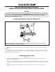
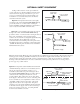
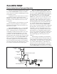
4. If an externally piloted pressure reducing valve is used, the control pipe should be pitched away from the PRV and installed at the pressure gauge on the shell of the heat exchanger. 5. A steam safety relief valve should be used prior to the heat exchanger if either or both of the following conditions exist. (1) If the maximum steam pressure could exceed the minimum water pressure in the tubes, or (2) The maximum steam pressure could exceed 150 psig (the maximum steam pressure rating of the shell).
Minimum line sizes to drain should be as follows: model 415 = 3/4", model 535 = 1", model 665 = 1-1/4", model 8120 = 2". Line sizes smaller than these will not allow sufficient flow for making high flow settings on the mixing valve. 5. 6. 7. A water temperature gauge should be installed directly after the by-pass drain valve. This thermometer is only used for inital temperature adjustments of the Flo-Rite-Temp or troubleshooting the unit. (See Fig.
OPTIONAL SAFETY EQUIPMENT See Fig. 3-1E for location of each option within the system. All options would be installed downstream of the water heater in the outgoing recirculation loop, if one is present, or downstream of the hot water thermal loop if recirculation is not used but always before the first hot water take off from the system.
IMPORTANT UNIT START-UP AND SHUTDOWN PROCEDURES Option #4 (Available only when a pressure reducing station is installed on the Flo-Rite-Temp). Using the Model GP-2000W1P system, when piped as shown in the Option 4 drawing, will provide a safe dependable shut down of the main steam valve when the water pressure fails or drops rapidly on the Flo-Rite-Temp.
4. Throttle the bypass valve to drain so that a constant 3 gpm of flow may pass to drain. 5. Slowly open steam valve or adjust the pressure reducing valve to allow 2 - 15 psig of steam pressure on the unit (CAUTION: always make sure there is water pressure on the unit before adding steam. Failure to do this will cause severe hammering of the unit and possible damage). 6. 7. 10.
down (Note: with water pressure on the unit the stem should pop back up after depressing it). If the HFT stem will not depress at all the valve is opened too far and you must turn the adjustment clockwise until there is 1/8" travel downward to the stem. 8. 9. With the unit now isolated from the hot water system and all flow of water being directed to drain, slowly increase the water demand to approximately 3/4 of the maximum capacity according to the capacity chart on page 13.
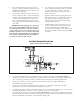
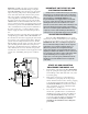
FLO-RITE-TEMP Recirculation System Piping and Operation Because of its relatively small size and compactness, the FLO-RITE-TEMP can easily be installed close to the point of water use eliminating the need for a recirculation system. Three-way Thermostatic Capsule - This device has a set point roughly 20 degrees below the set point of the FLO-RITE-TEMP and will maintain the temperature in the loop between the set point of the capsule and the set point of the FLO-RITETEMP.
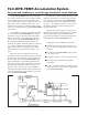
FLO-RITE-TEMP-Accumulation System For peak load conditions or to avoid large intermittent steam demands The FLO-RITE-TEMP water heater accumulation system is designed to provide a specified volume of accumulated hot water for short duration peak loads or when steam is in short supply and a recovery time can be tolerated. During periods of low or no demand, the water in the accumulator tank is heated to the set point temperature by the FLO-RITE-TEMP water heater.
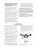
Flo-Rite-Temp Tempered Water Systems For Safety Shower/Eye Wash Stations The problem which faces many companies today is how to safely warm water to be used effectively in a drench shower or safety shower situation. adjusted set point within this temperature range, usually the lowest set point of 120O degrees is used). The 120°F water can be piped to the Rada Z358 thermostatic mixing valve which will blend cold water with the 120°F water to make the tepid water for the safety shower/eye wash station.
Single Wall and Double Wall Profile Model 415 and 535 Profile Shown (665 and 8120 valve shows that connections for water inlet and outlet are on opposite sides of the valve body). Fig. 12-1 Table12-1. 12-1.
FLO-RITE-TEMP Table 13-1 CAPACITIES AND STEAM LOADS Standard Hot Water Capacities* Steam Capacities Inlet Set Steam Pressure Steam Pressure Temp. Temp.
TROUBLESHOOTING GUIDE Table 14-1 Problem Causes Solutions The steam is not turned on to the unit. The water tubes in the heat exchanger are Only cold water plugged. comes out of The differential pressure sensing diaphragm the unit. is ruptured. The mixing valve is not properly adjusted. The steam pressure is too low. Air has accumulated in the shell of the heat exchanger. Only warm The flow is above the rated capacity of the water comes unit. out of the unit. The tubes in the heat exchanger are scaled.
Single Wall Heat Exchanger - To remove the tube bundle for cleaning. Simply unbolt the mixing valve from the shell and move it out of the way. The tube bundle can be pulled out from the valve end (see Table 12-1 for clearance dimensions). Once the tube bundle is out of the shell, unbolt the end cap on the floating head end and remove to provide straight through cleaning.
Clean-In-Place Operating Instructions When there is a noticeable drop in the Flo-RiteTemp’s — hot water capacity, temperature, or an increased water pressure drop across the unit — tube bundle scale removal should be considered using the commercially available product called RITE-Qwik*. Tube bundle scale removal can be accomplished as follows: Step 1 - Shut off steam supply valve #1 to the Flo-RiteTemp.
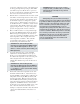
665 Control Valve 8120 Control Valve 16 16 17 18 15 32 19 17 15 20 19 18 14 14 32 21 20 22 21 13 22 13 12 11 23 12 11 23 24 9 24 9 25 33 25 8 26 7 8 10 26 6 6 5 27 5 31 30 29 28 4 3 2 1 3 2 30 29 28 1 31 Listing of Parts Number Description 1 Spring Adjustment 2 Spring Housing 3 Spring 4 Lower Diaphragm Cover 5 Diaphragm Bolt (12) 6 Diaphragm Nut (12) 7 Upper Diaphragm Cover 8 O-Ring 2-155 9 Lower Valve 10 O-Ring 2-147 11 Set Screw X2 12 Body 13 Stem 14 HFT
415 Control Valve 535 Control Valve 16 16 17 15 18 14 15 19 20 32 17 18 19 33 13 21 13 20 14 21 22 12 22 12 23 23 11 24 11 10 24 25 9 25 7 26 26 8 27 27 9 8 7 6 5 5 29 31 4 3 2 28 28 31 30 30 4 1 3 2 1 32 Listing of Parts Number Description 1 Spring Adjustment 2 Spring Housing 3 Spring 4 Lower Diaphragm Cover 5 Diaphragm Bolt (12) 6 Diaphragm Nut (12) 7 Upper Diaphragm Cover 8 O-Ring 2-153 9 Lower Valve 10 Lower Valve Disc 11 Retainer Nut 12 Body 13 Stem
Notes 19
Limited Warranty and Remedy Armstrong-Yoshitake, Inc. (“Armstrong”) warrants to the original user of those products supplied by it and used in the service and in the manner for which they are intended, that such products shall be free from defects in material and workmanship for a period of one (1) year from the date of installation, but not longer than 15 months from the date of shipment from the factory [unless a Special Warranty Period applies, as listed below].